@ChelanJim , you are my hero, that was my exact problem! When I watched Langmuir’s tutorial on how to setup the plasma cutter, I just put in the information as they did it, not realizing that my kerf settings and nozzle diameter were in the reverse order that they were in the tutorial. Everything appears to work perfect now. Thank you!
2 Likes
So I had my kerf as 1" and my nozzle diameter as .055"…![]() #rookiemistake
#rookiemistake
2 Likes
Most of us have made similar mistakes. I set my pierce delay at 0.06 seconds and had all sorts of trouble cutting out things. Like you, I was a whole magnitude off as the pierce delay was suppose to be 0.6 seconds.
You might also get in the habit of setting your nozzle diameter and kerf setting to the same thing (0.055) for Manufacturing in Fusion 360. The reason being is that the current simulation seems to show a better visualization of the cut if the nozzle is not so noticeable.
And the last “also”: your kerf setting should eventually be determined thru testing and this will change with each metal/thickness/power setting.
Two tried and true methods to get your kerf setting dialed in are:
- Cut a straight line. Measure the line. That is your “kerf.”
- Cut out a square such as 2" x 2". Measure with calipers. Increase your kerf setting by 50% of your under-cut amount if you are under 2.0 inches (moving your stream away from the contour). Decrease your kerf setting by 50% of your overage if you are over 2.0 inches (moving your stream closer to the contour). So if it measures 2.1 inches you would subtract 0.05 from your kerf setting.
Not really. There were three more people waiting to answer your question.
3 Likes
Ok, thanks for the info, I’ll see what works best as I move through learning about it all.
Well maybe so, but you helped me first so you get the honors.![]()
1 Like
How can I post a video here won’t let me?
You have to post a link to where the video is located, it won’t let you upload a raw video. The closest thing you can get to is uploading a gif which probably isn’t going to help you.
YouTube, Vimeo, or Twitch are good options
Tin makes it look easy doing stuff live.
1 Like
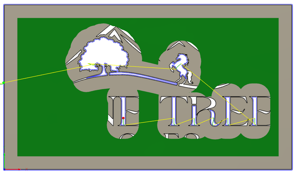
i feel like the answer to my lack of tool path might be to just use my sheetcam but trying fusion 360. complete novice on both platforms. this thread has been amazing and learned a lot but still getting partial path after changing lead ins, using sketch contour and many other tweeks recommended. any other advice for my farm logo?
farm logo v1.f3d (1.2 MB)
Oh boy…this is going to be a fun one! First off very nice look to the design but not so plasma cut friendly. I’m going to cover a few things quickly and might miss some other important things to know but sure others will chime in with even more experience.
Read entire post because there are a couple critical things to understand about cut paths. Many factors come into play deciding and you have multiple things that complicate this cutting.
Factors
- how thick is steel going to be? reason this matter is because strength in tabs and area needed between the lines.
- size of design - design is 10.5" x 6" which is pretty small
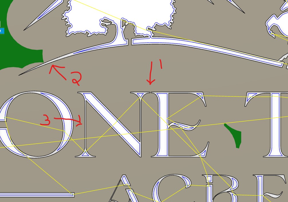
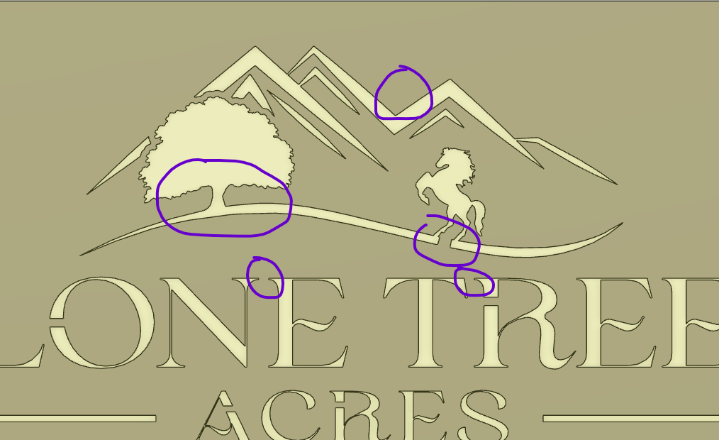
Your design - left compensation -
#1 - try to add spacing when doing letters.
#2 & #3 - you won’t get a cut in this area because it’s too close together.
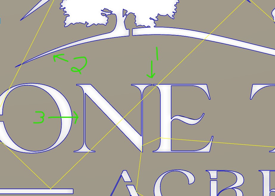
Your design - center compensation -
#1 - if you cut this on line it will burn to next line
#2 & #3 - you can see this one will cut line as you want
So after reading all of the above I went ahead and did a couple quick changes to design to show you some options and explain my thought process when designing this stuff.
Here is your design in red
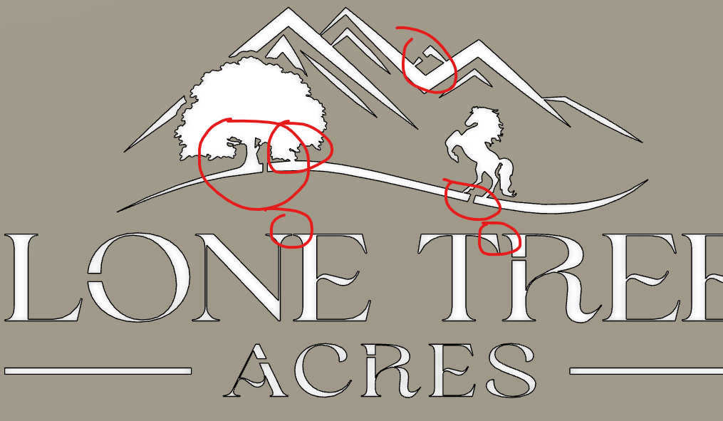
Here are couple changes that I did so you can decide if you like them or not. The tree is great example of not needed bridges that might take away from look of your design. Unless you those branches are needed than just do away with them. Same goes for extra triangle for the mountain. All that bridge will do is catch your eye and take away from design. I added a little space between a few of your letters and but still really close due to the overall size of your design. I also modified the “R” a little.
horse design dp.f3d (1.2 MB)
Just because a cut path is generated and shows green don’t mean everything will make it. As you start designing and cutting, you’ll start understanding how close you can cut and limitations for different thickness of steel. Good luck and post your design if you end up cutting.
6 Likes
This is amazing help and I’ll read through the original posts again as I’m trying to soak it all in but I’m sure I missed some key advice. Thank you so much for the help and explaining some of the design/functional plasma limitations as maybe this would have made a better t-shirt design ![]() I’ll try the file changes you made and see what comes out but just amazed at this community and your support!
I’ll try the file changes you made and see what comes out but just amazed at this community and your support!
1 Like
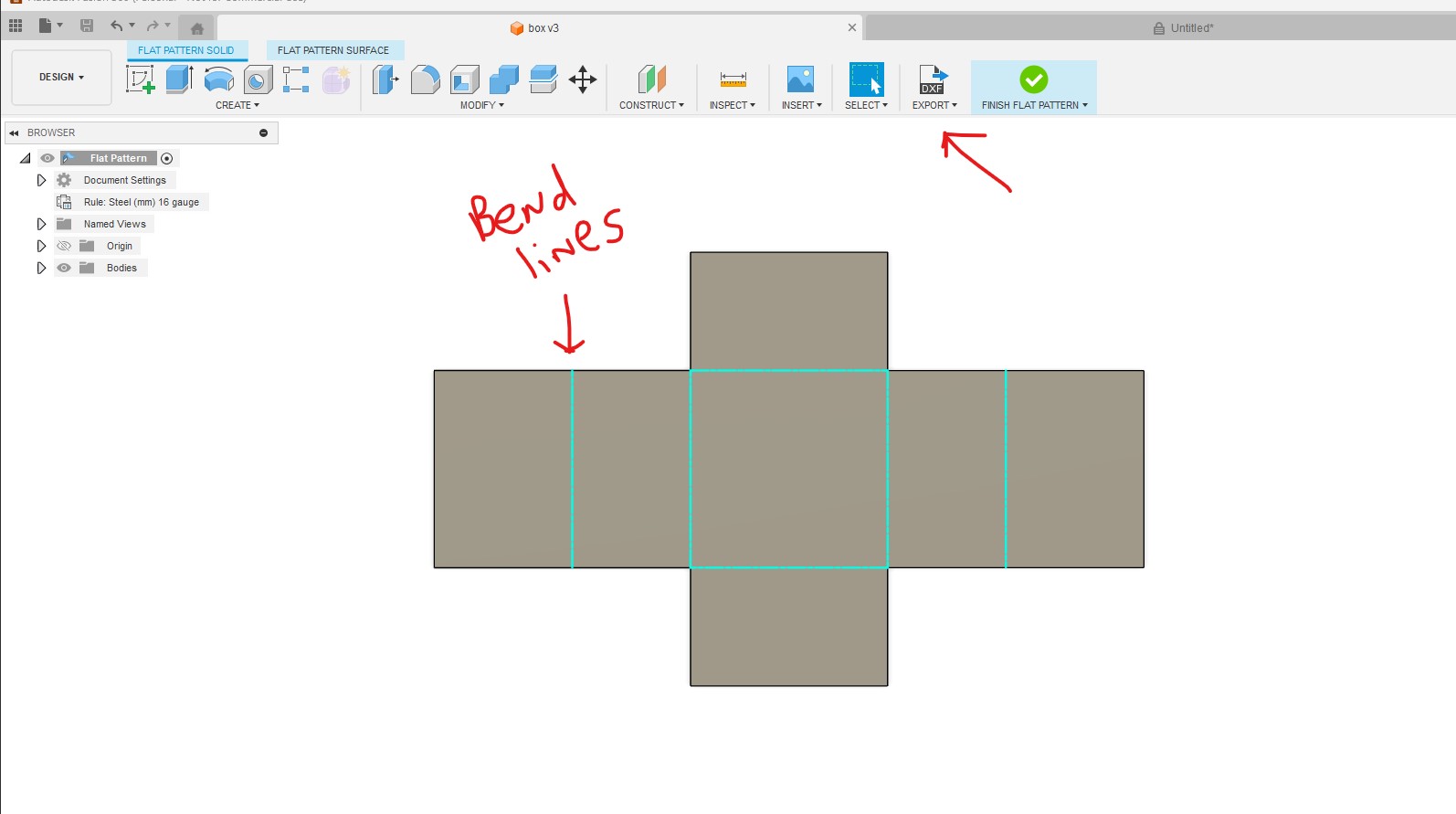
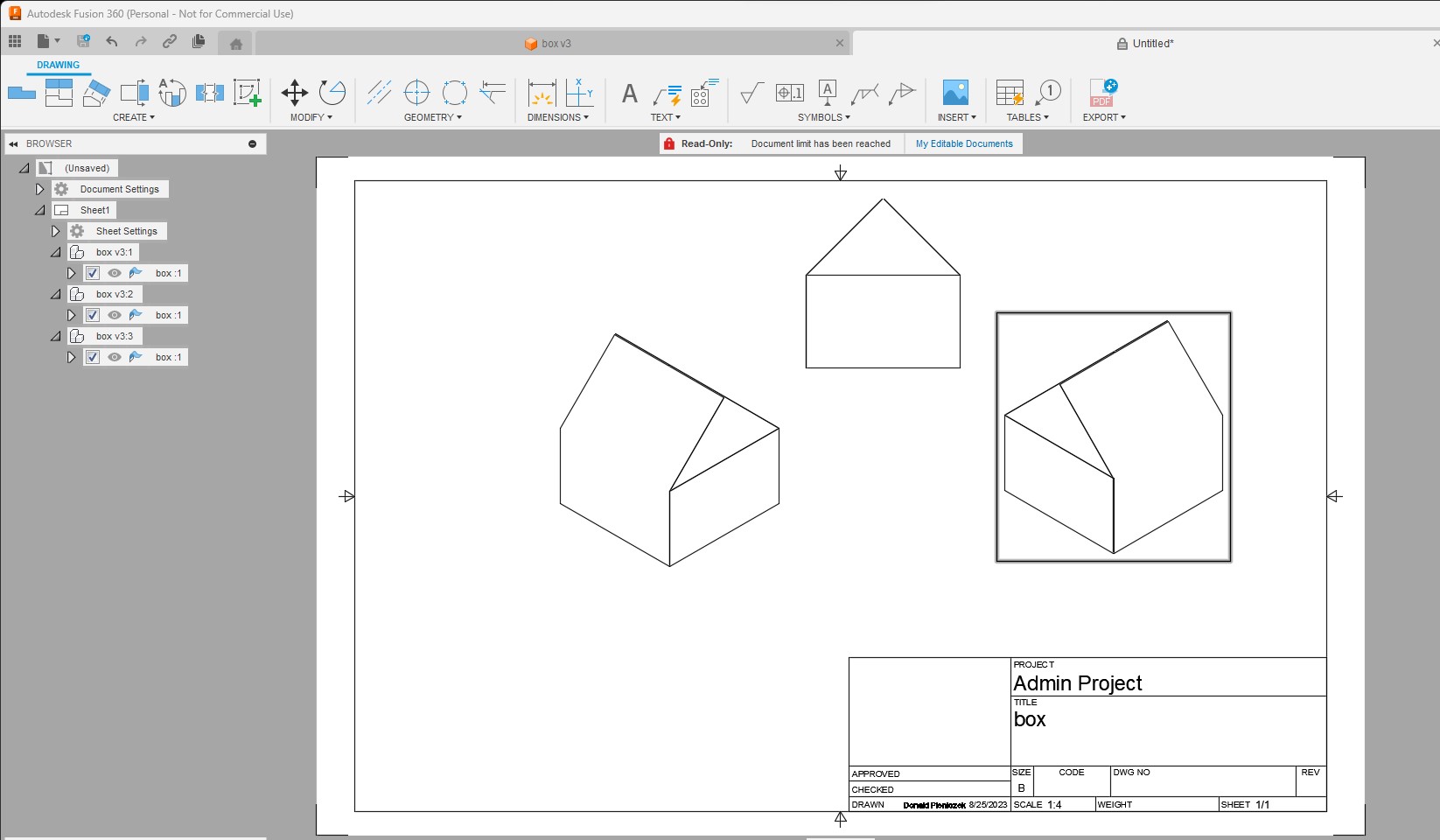
Next month I’ll have 1 year of playing around with fusion and plasma cutting. No training or no help besides @TinWhisperer showing videos. I have never used sheetcam myself, but fusion can be hard at the start but once you figure out basic 2D stuff you can create things in 3d that are really cool in minutes. So, my point of doing this 5 min box in 3D below is so you don’t give up on fusion because the things you can do with it are endless. 1 button and it all lays flat so you can cut it.
box_.f3d (193.6 KB)
box.dxf (6.0 KB)

3 Likes
That seems like the dark arts… ![]() magic for sure and I didn’t even know something like that could be done. Pretty amazing. I’ll keep cracking at it for sure and I have a 3d printer which also makes some fabrication here in 3d also important!
magic for sure and I didn’t even know something like that could be done. Pretty amazing. I’ll keep cracking at it for sure and I have a 3d printer which also makes some fabrication here in 3d also important!
3 Likes
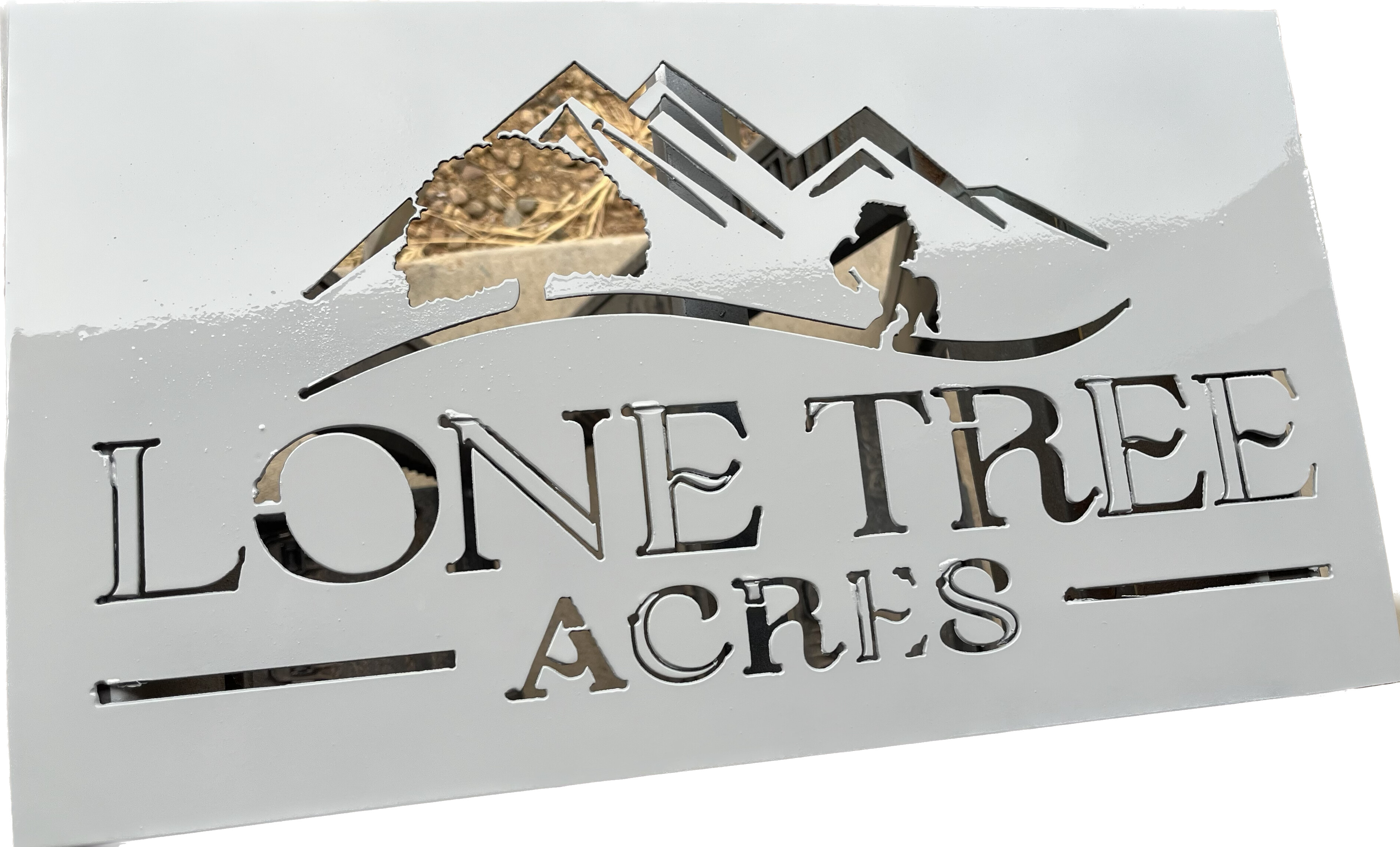
Still have some work on my end to clean it up on the letters but I can see your point now clearly in the cut. I did make it ~10x18 so that helped for sizes. I’m always amazed even small sizes how much detail the XR can make for the tree and horse. I primed it so it was easier to see the details of work to change stuff. Thank you again!
2 Likes
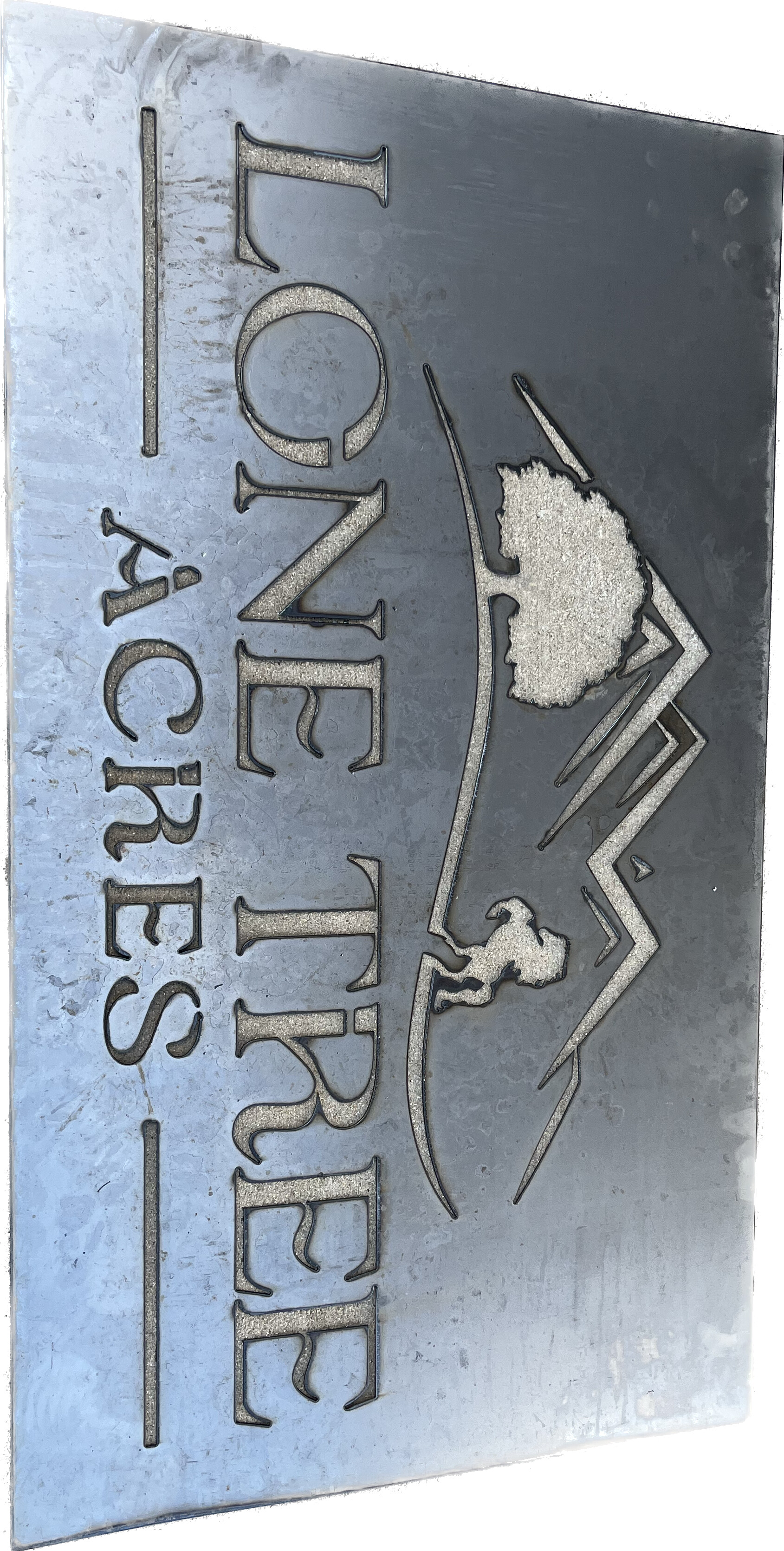
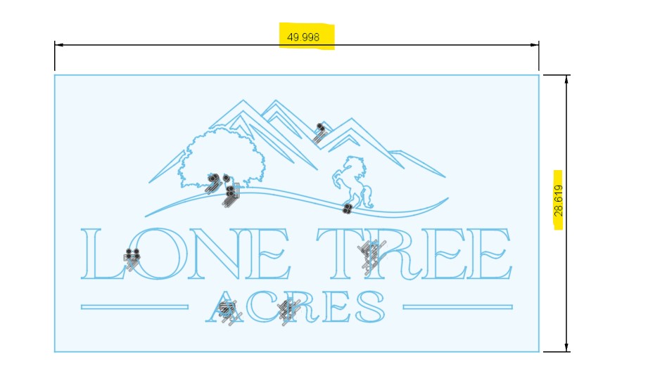
I went back to the original svg file and tried to repeat from scratch what you showed me. I also took the original and blew it up to 50x30 in for the sign size I needed. Turned out pretty darn good for a newbie!
2 Likes
Looks great!
How are you hanging it?
I haven’t mastered a through hole yet in cad. Was planning on welding this to a square pipe frame. I also have been drilling holes which I realize seems caveman when I have a plasma table.
2 Likes
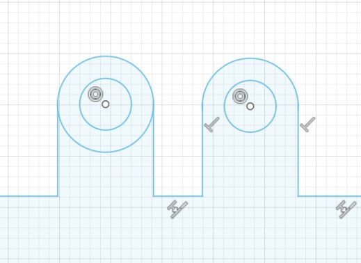
A really easy type hanger takes literally a few seconds to make. Just draw two concentric circles, add a tangent line down each side, the trim away the bottom part of the larger (outer) circle.
The one on the left show both circles before trimming and the right is finished.
2 Likes
That sign is 50x30? wow thats a big sign.
Cut that on a XR?
Did turn out good
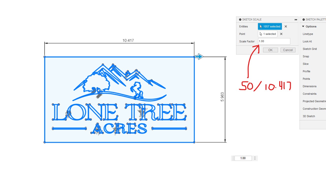
Not sure if you did this to make your original measure 50" but super easy to get things the size you want them.
1 Like
Yes on the XR it turned out great. I think with the finer details based on DonP’s statement there is some significant economy at scale.
DonP I did that exact thing but it seems like I can only find that option when just starting new files when importing. I have a heck of a time changing dimensions any other time in a sketch. Youtube videos make it look so easy and it never works that way for me when I go to dimensions and things don’t pop up like the tutorials act.
1 Like