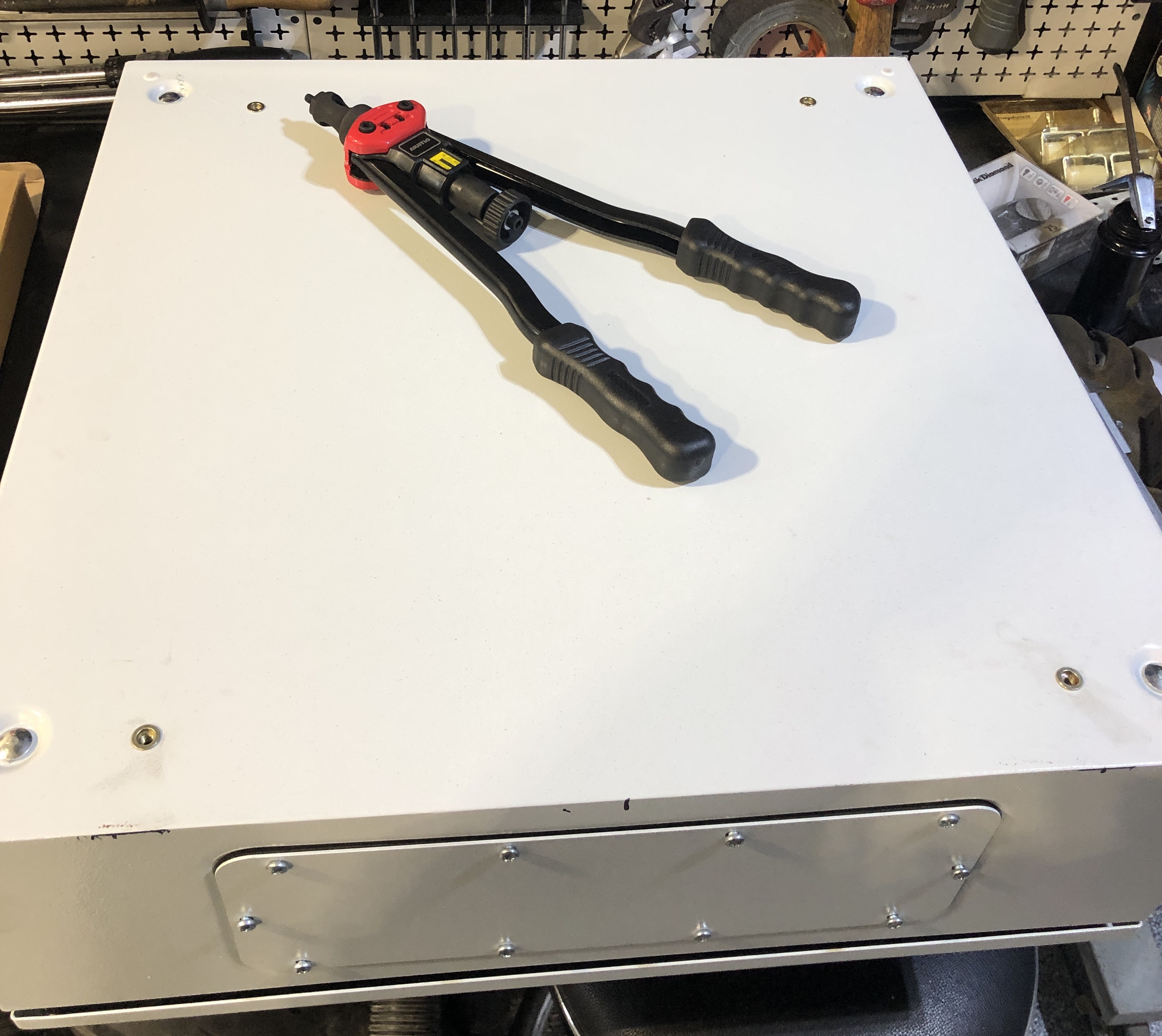
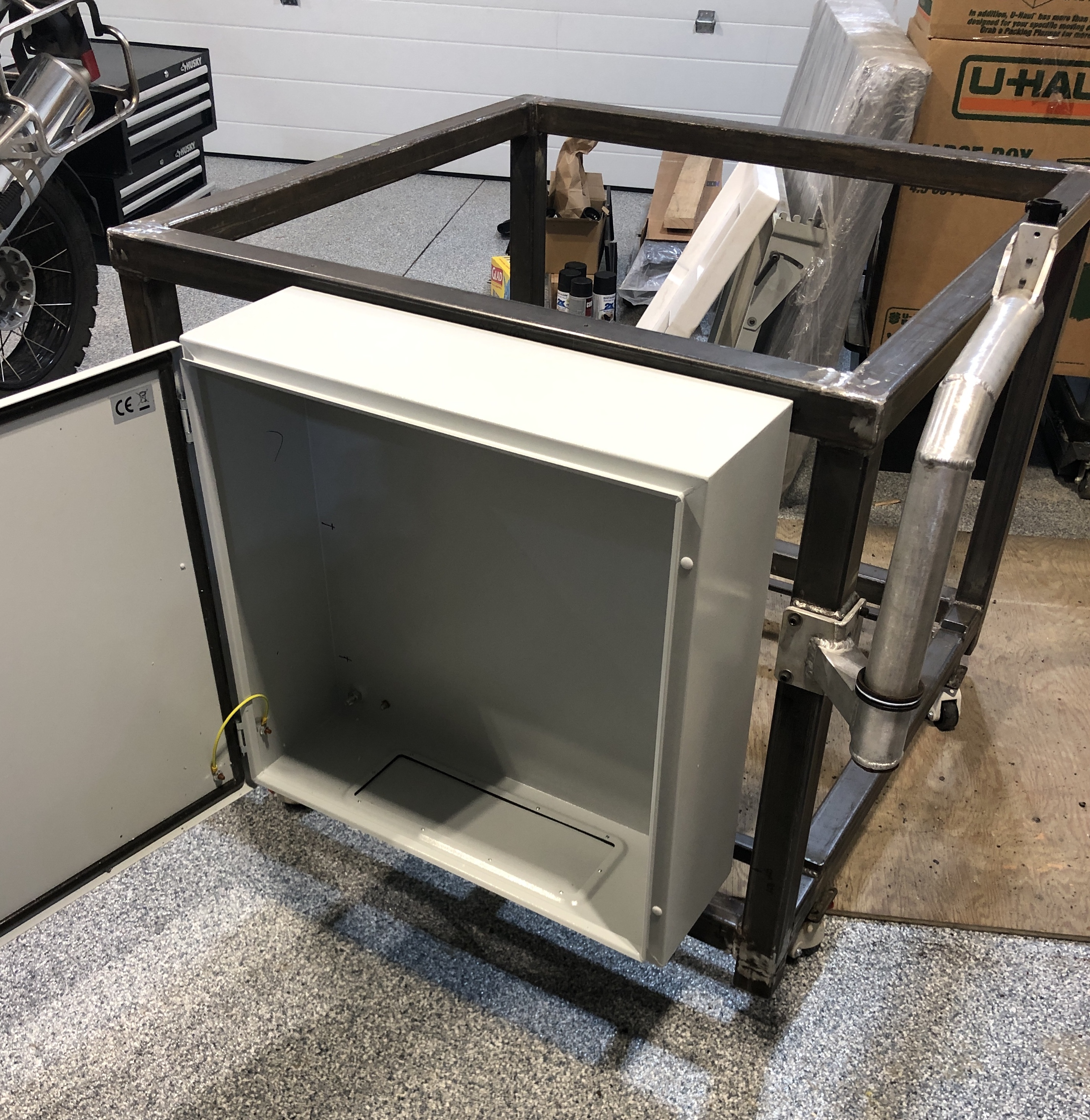
Drilled some holes in my new control box today and installed some rivnuts. Now it’s ready to install on the MR-1 frame.
1 Like
What spindle did you pick, and what are the specs? Welcome to the very small club of those of us using third party spindles. I think you are the first to use BT30 (my spindle uses ISO30, MrMachineTx has a spindle that uses ISO20).
It’s a Jianken JGY-5.5/100 PMSM spindle if I recall correctly. High torque, low speed. It has the same torque rating from 0 rpm to 15000 RPM but it drops off a bit from there to its max. speed of 24000 RPM. 5.5 kW, 100mm OD body. It has nearly double the torque of a non permanent magnet synchronous motor from what I could tell. You can get it with an encoder too. The BT30 connection will be nice. I’ve already bought some ER32 collets and even some shrink fit tool holders to try out.
Alex looking for some advice. Retro fitting my MR-1 with a new spindle, acorn controller and clear path servos … do I just assemble everything with the stock langmuir stuff so I can get the machine running and machine any odds and ends I need for the retrofit or do I just jump in and start canabolizing the langmuir control box and build the machine with all the upgraded stuff?
That’s really up to you. I reused some stock components (cabinet wiring, steppers, probe, etc), so in my case it was advantageous to get it all up and running as a stock machine first. This also gave me a chance to check for any warranty issues and to machine some motor mounts before rebuilding it all with new stuff.
For instance you’ll almost certainly want a working machine to machine the motor mounts for your updates, unless you happen to have another mill (manual or CNC) on site.
That’s a good looking spindle! It’s a little heavier than stock, but since you are upgrading the servos you’ll probably be okay. I would oversize the Z servo.
Also since you haven’t poured concrete yet you might want to think ahead about your interest in doing automatic tool changing and where you will put the tool rack. You could set a trench in the concrete for tools to live in since BT30 tool holders are so tall.
1 Like
Excellent advice Alex. Especially about over sizing the z axis motor and planning for an atc system in my concrete work. In fact, I probably need a running mill to build the atc system to. You have me thinking now. Maybe I should put a motor brake on the z servo too. It won’t lock up like a stepper will to hold position. The z uses a lead screw not a ball screw but that might not be enough.
A gas strut to lift the heavier Z may also be an option. I haven’t tried this, but was watching a “This Old Tony” video about his new CNC conversion of some old iron where he used them. I’m tempted to play with that on my machine to see if I can increase Z speeds and reduce the chances of stalling (the Z axis is the only one that I’ve ever had stall).
I don’t have a good memory of where there is metal framework under the concrete. A trench at the back of the table for holding collets would be ideal. I would order some tool holding fingers now to be able to measure the movement necesary in Y to pull a tool out, that will help you figure out desired trench width. Ideally I’d make it at least 2 inches deep. My guess is that 24" wide by 2-3" long by 2" deep would be good. You can probably find something on Amazon to embed that is about that size, but you’ll need to make sure that the Y axis can reach that whole area (I think you’ll need to slide the table forward about an inch). Your motor probably sticks out farther from the Z slide than the stock motor, so take that into account too.
The limitation with gas springs seems to be finding one which allows for fast cycling and which has low enough spring pressure. McMaster-Carr doesn’t have any good options – the ones with suitable spring pressure and extension are limited to 6 cycles per minute or 36ipm. Stronger ones support 40 cycles per minute (240 ipm), but no for a 6" stroke length.
Wow Alex you really brought up some nuggets of gold for me to think about. I never really considered the new spindle mount might stick out further that the stock one. I actually assumed it would be the same or even less. And I really like the idea of a pneumatic cylinder to assist up z movements. I actually have some cylinders kicking around too. I can wire an acorn relay to pressurize a pneumatic cylinder with air when ever the z motor spins in the up direction!. Regarding the ATC design, I’m resistant to making a trough as it’s just a place for coolant/chips to collect and it reduces the mass of the concrete base for damping. I’ve got an idea in my head to deal with the long bt30 tools I just have to make a solidworks model to get all the details sorted out. One thing cool I discovered about having BT30 … I can now go to the Tormach website to get relatively decent tools at a reasonable price. I also discovered you can by a fantastic Torrmach coolant system super cheap. Complete with pump, coolant reservoir and chip collection pan!
1 Like
1 Like
I’m curious to hear your idea. One that I’ve come up with is setting certain paths that the system can use to get to the tool changer rack where the Z slide needs to be all the way to the right to go to the back of the table. Then it can move along Y to the correct tool. You can fit 5 (maybe 6) ISO30/BT30 tools this way, have them out of the way, and build a chip shield to keep chips off of them. It’s just some programming complexity.
I’m still using my machine as a quick change system. I’ve done ATC as proof of concept, but the quick change system (where I operate the drawbar while the program is paused on tool changes) is very reliable and fast.
Thanks for the links, I personally run a fogbuster-like system instead of flood coolant. It’s a better setup for how I use the machine.
I’m toying with two ideas:
-
A wine rack located at the back of the machine. The tools laying flat with their business end facing towards the front of the machine. Because the tools are laying flat, they can easily advance forward under the gantry on guides via pneumatic cylinders . After advancing forward past the bridge, a mechanical linkage tips the wine rack upright so the tools are vertical for easy access by the spindle nose.
-
A carousel under the chip tray that rotates the desired tool into position to be passed to the spindle nose via a 2.5” pipe hole that goes right through the concrete. Again, a pneumatic cylinder would push the tool vertically threw the pipe. I’d put a tractor exhaust flapper of sorts on the pipe to keep coolant out.
Just ideas at this point though.
The other one that I’ve thought of is similar to your second option. There is a lot of room at the back of the machine to build a partial circle carousel that rotates forward and then turns back out of the way when complete. Your version with the pipe hole is interesting though, that would keep chips completely out of the way, but requires a 2-stage system (rotate then lift) which adds more complexity. Personally I’m sticking with QTC for the time being.
I do have a wine rack at the forward end of the machine working, I just haven’t solved chip management yet.
1 Like
Got my wireless touch probe in mail today.
Tough to beat for the price. Out of the box, the quality looks exceptional. Can’t believe the price
3 Likes
Let me know how it works. I tried a quality after-market probe but could not get to work with the Langmuir control strategy. Hopefully, this will be the answer.