I have a new build of the MR-1 and I am at the point of squaring the Y rail/gantry. Per the video I have the mini PC configured, CutControl Installed (v22.1.1/f 1.4), and the right Y rail loosened. Once I start CutControl I am prompted to home the machine or bypass. I select bypass which clears the alarm but now I have a status of Hold_0 being displayed. I have checked the connections visually and by pulling on each cable/wire to see if any were dislodged, and there are no issues. I can trigger the limit switches, and clear the alarm, but Hold_0 is still displayed in the status area. Have any of you run into this issue? If so, what was the fix, or action taken?
I was sent a new controller board, but that was not the issue. I can connect to the MR-1, I can even home it. If I try to home again it just sits there with the wait indicator spinning never commanding a homing move. To exit I must go into Task Manager and end the process. If I proceed without homing, then attempt to home, the same thing. I am at the step where you align the Y rail and then the gantry, but can’t because the status always shows Hold_0.
Has anyone else run into this issue? I did find 1 instance where someone with a Crossfire Pro had this issue but there is no resolution within the post and it was back in August of 2021, even mentioned it to Jake.
As far as drivers for the Com Port in use; what driver is being installed on these of you that have had no issues, is it the standard Microsoft driver or is it an Arduino specific USB driver?
If anyone has any ideas I am all ears. So far I’ve tried using a different com port, tried using a different USB B cable (from mini PC to controller enclosure), and I have even installed the latest OpenJDK v17.0.7, and writing the environment variable (points to the location of the java SDK), as a long shot.
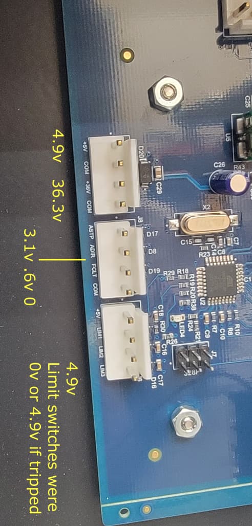
I have since checked the power supply and confirmed that there are 36v to the board and 5v coming off of the board. One thing I’d like to confirm is that the Y2 driver only sees 1.7v (standard driver) or 2.8v (high power) on the +Pull side, whereas Y1 sees 4.2v on +Pull. Y1 and Y2 see 4.2v (standard driver) or 4.6v (high power) on +Dir. With X and Z there are 4.6v on +Dir and 4.6v on +Pull.
Any suggestions on what else to check are welcomed.
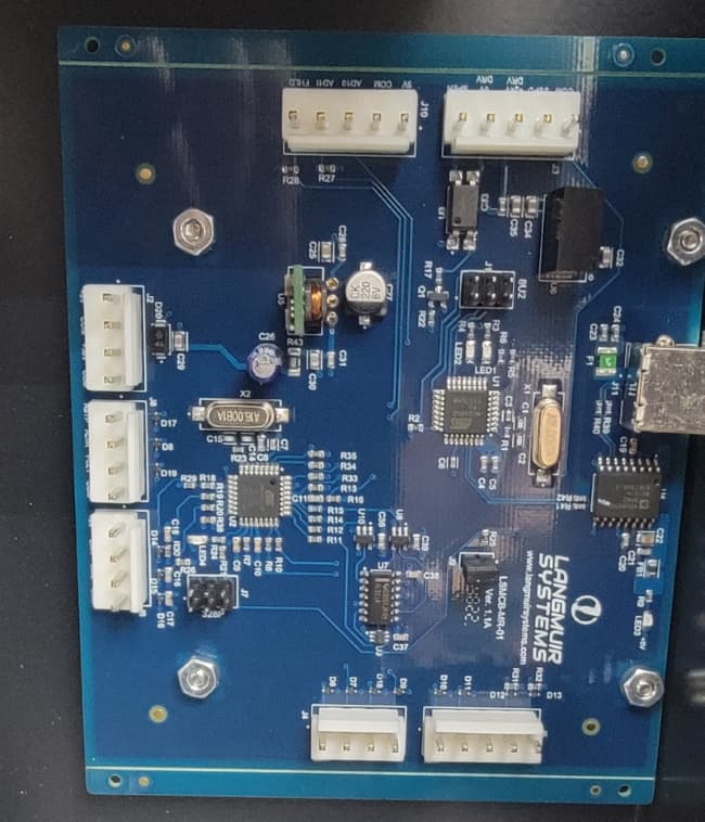
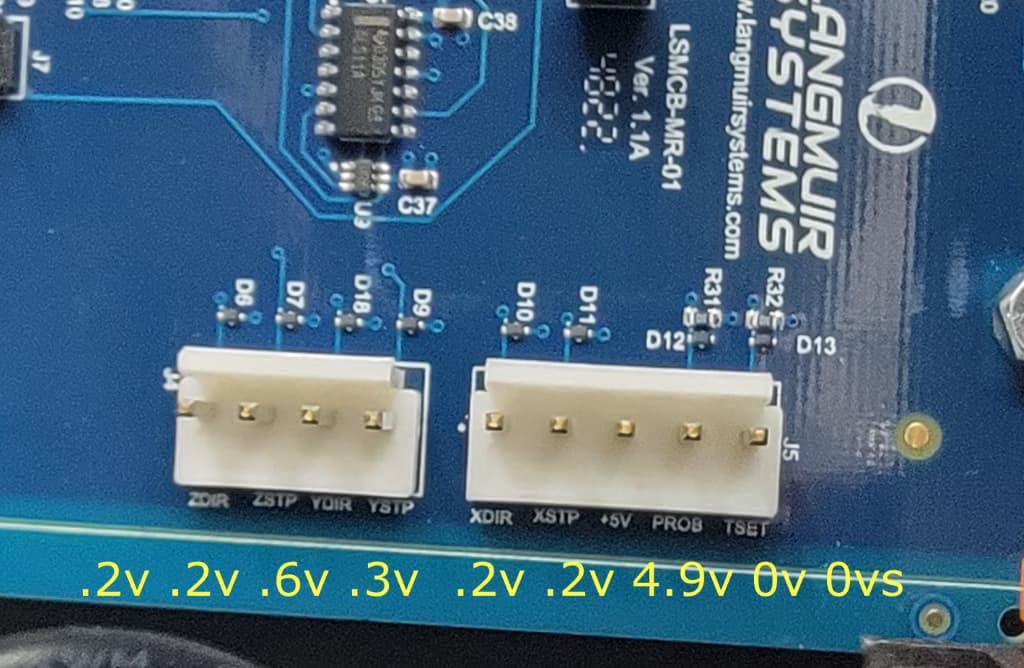
Below are images denoting probed voltages and an image of the entire board for the purpose of verifying no missing jumpers or visible issues with the PCB.
When you say PULL do you mean the STP pins on the control board? I think they are labeled PUL or pulse on the driver. Those are a pulsed square wave, so measuring them with a DMM probably won’t work very well. I’m not sure that it is deterministic if they’ll end up on a high or low pulse.
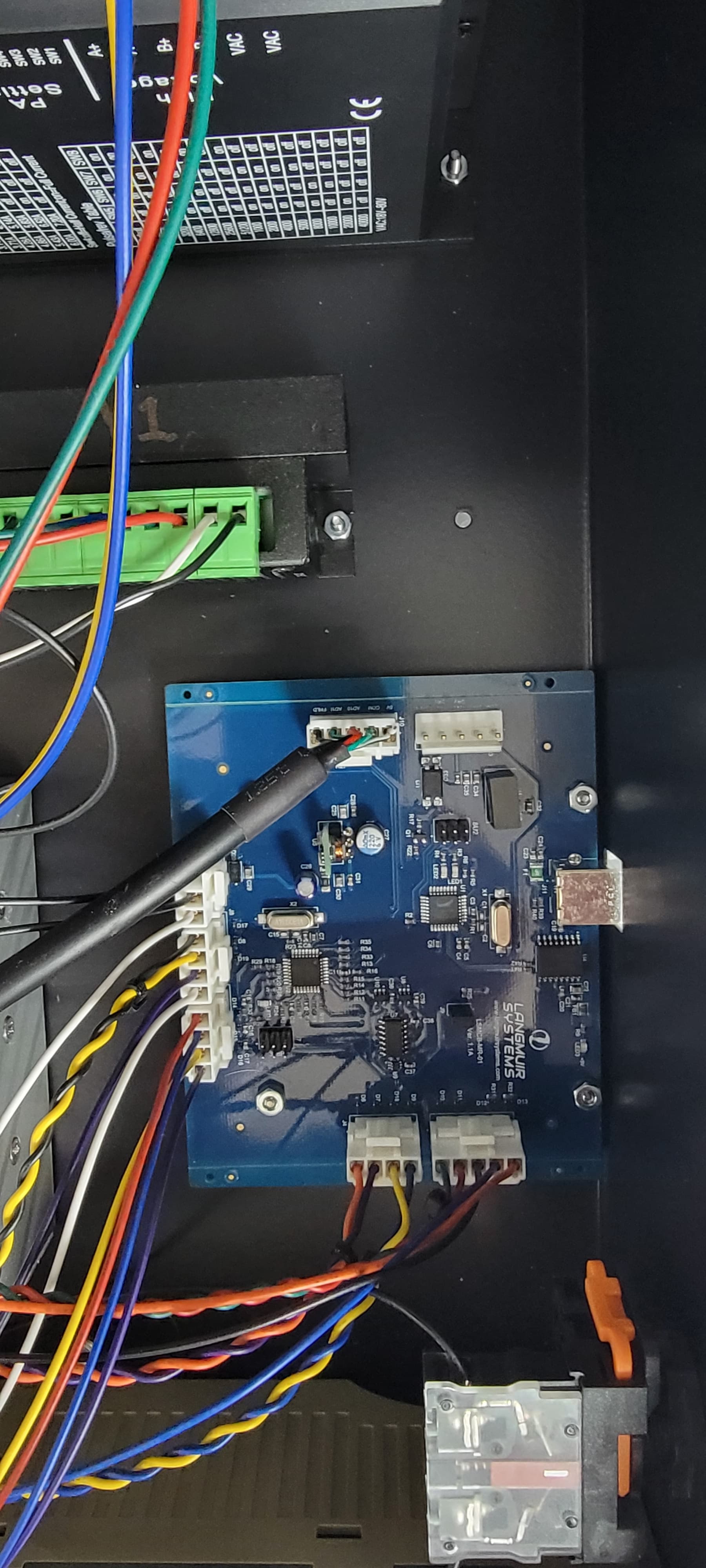
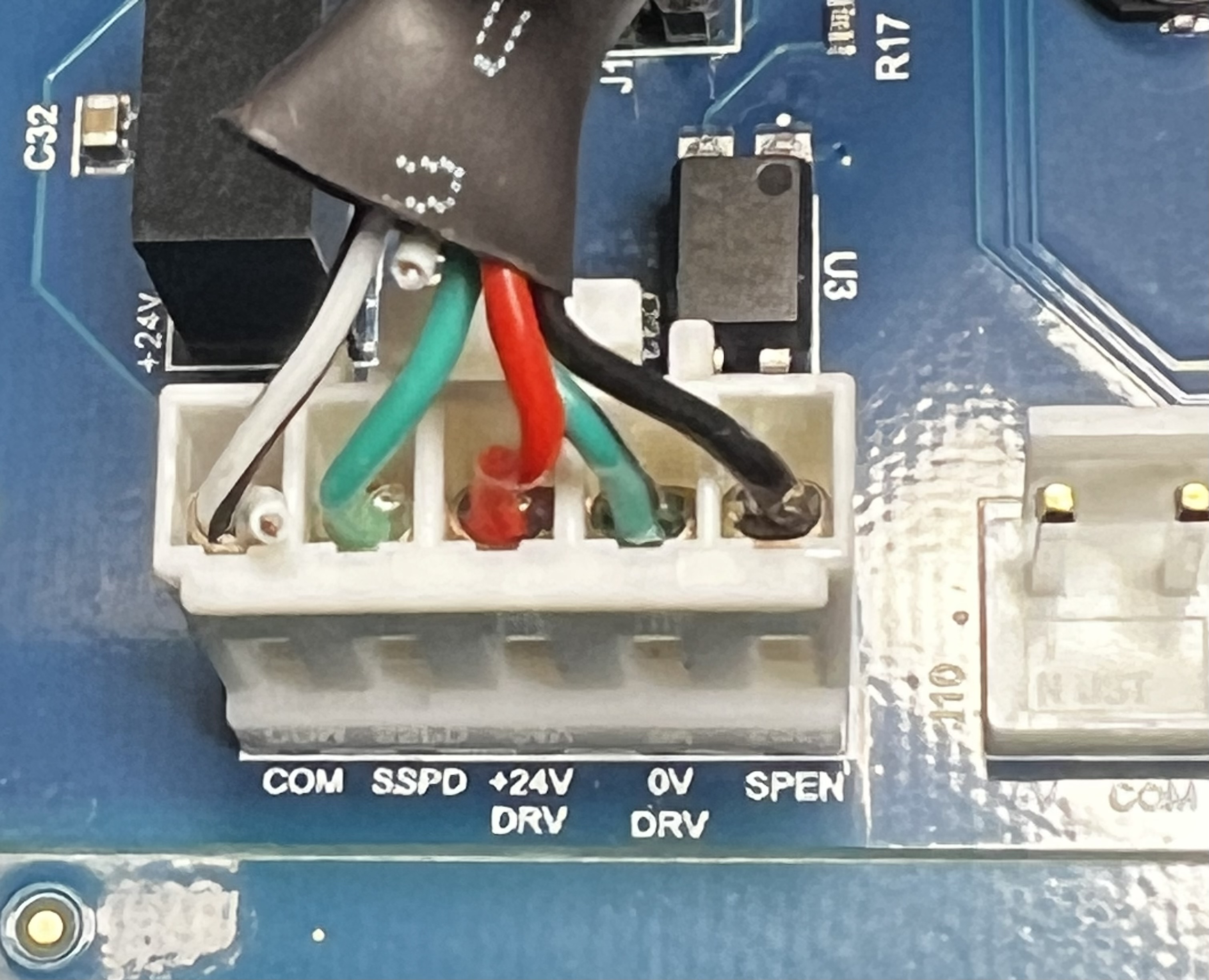
I think your machine was mis-wired. There should be no connector on the J10, and the one next to it (with SSPD and SPEN) should be connected to a wire that goes to the spindle. J10 is the spindle encoder signals, which they didn’t hook up (at least on my machine).
The 36V input on that board is used to generate 24V output to enable the spindle driver. The spindle speed is 0-5V or 0-10V (I forget which) analog signal on SSPD that corresponds to 0-8000RPM.
There has always been a connector on J10, it goes down to the VFD for the spindle and consists of 5 individual wires. If it isn’t a problem, would you mind taking a picture of your wiring. I’ll compare it to mine.
I’m glad you figured it out. Luckily I already had this picture on my phone – I’ve rewired my MR-1 around a different control board so I wouldn’t have been able to take a photo now.
Langmuir did a nice job of labeling every pin on their board.
You wouldn’t consider sending me the old one? Its been days since I have had a response from Langmuir and I am completely broke down. I am hoping a new controller will fix it but who knows. I ran 4 parts the other day and the 5th part the bit went right across the middle of the part and destroyed it. I need to finish this stuff and do not want to take anymore chances.
Indiana. Brother if you have a spare board that you would consider lending me all you would need to do is PM me with your address an email and I will do everything else. You will just need to give me box size and weight and print a label. I will do everything else
@Rufus I have a control board I could lend you, and I’m in the Indianapolis area, if it makes things simpler or quicker. My machine is in the middle of a Centroid Acorn rewire here.
Thank you sir that is extremely thoughtful. Langmuir finally emailed me 20m ago and is now sending me one but if they fail on me I will keep you in mind. If your ever in the Nashville area yell.
I am having the same issue, Status “hold_0” Everything worked as it should yesterday, i powered down everything and when i turned it on today this is what i get. The machine will home its self and thats all.
Any thoughts?