I have the stylus tip dialed in to a couple 10ths. I probed in X and Y, and the only part of the probe that is touching is the stylus ball, not the stem. I verified X and Y position with a wiggler. Probe reading is out by +.009 in Y, and +.0115 in X. How do I get this dialed in?
Have you set you axis travel compensation? Step 23 in the assembly guide. Might be good to double check this again with a 1 2 3 block if already done?
1 Like
You might try this:
1 Like
Here are some pictures of how it works. Loosen the top screws just a little. The side set screws will only move a 32nd or so. Move it right, loosen the left screw, and tighten the right. Get It?
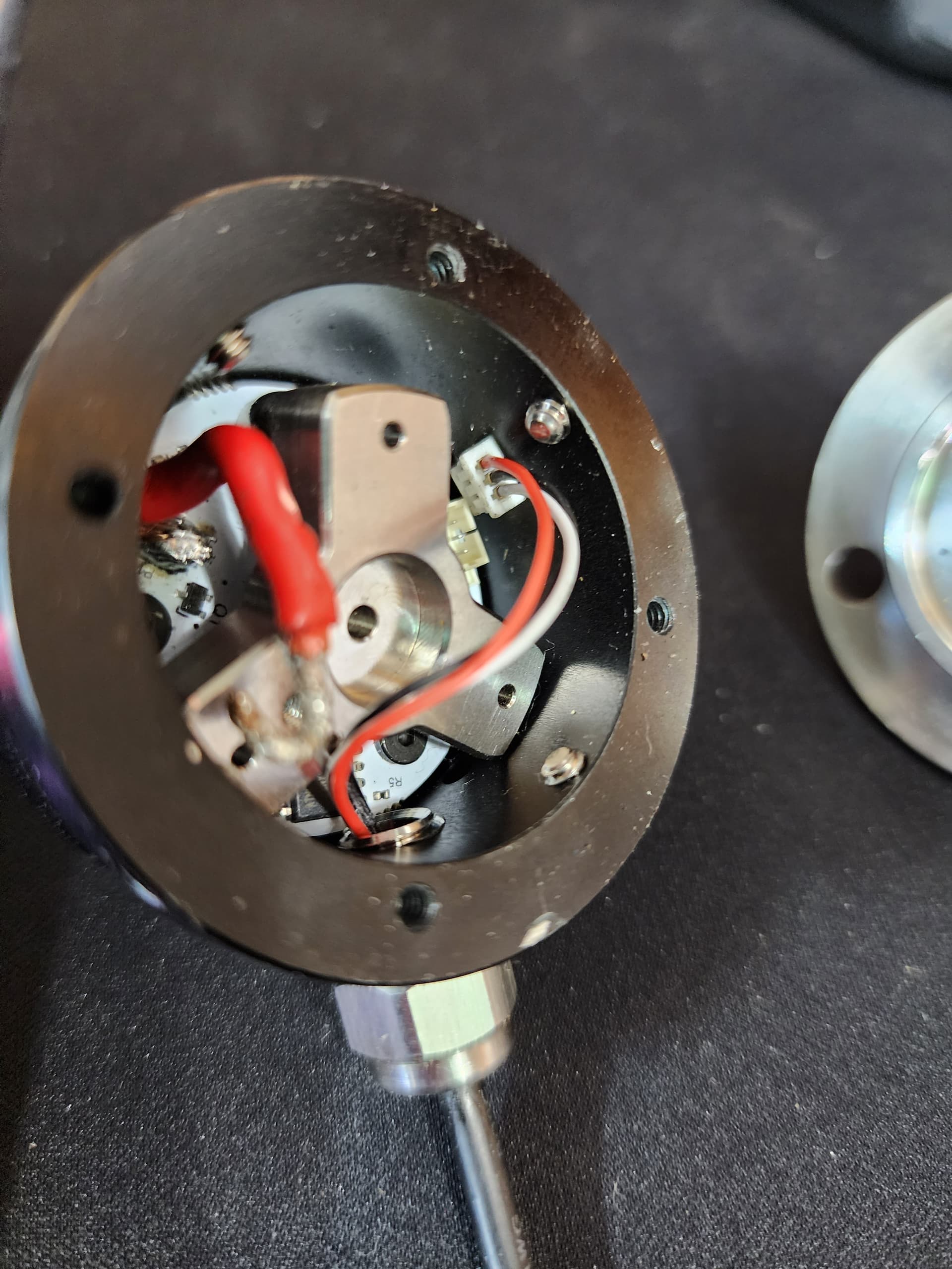
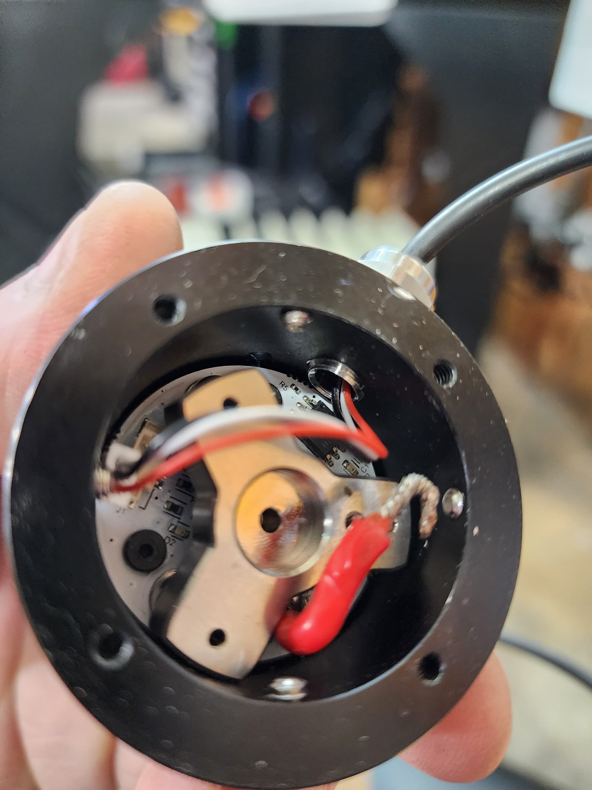
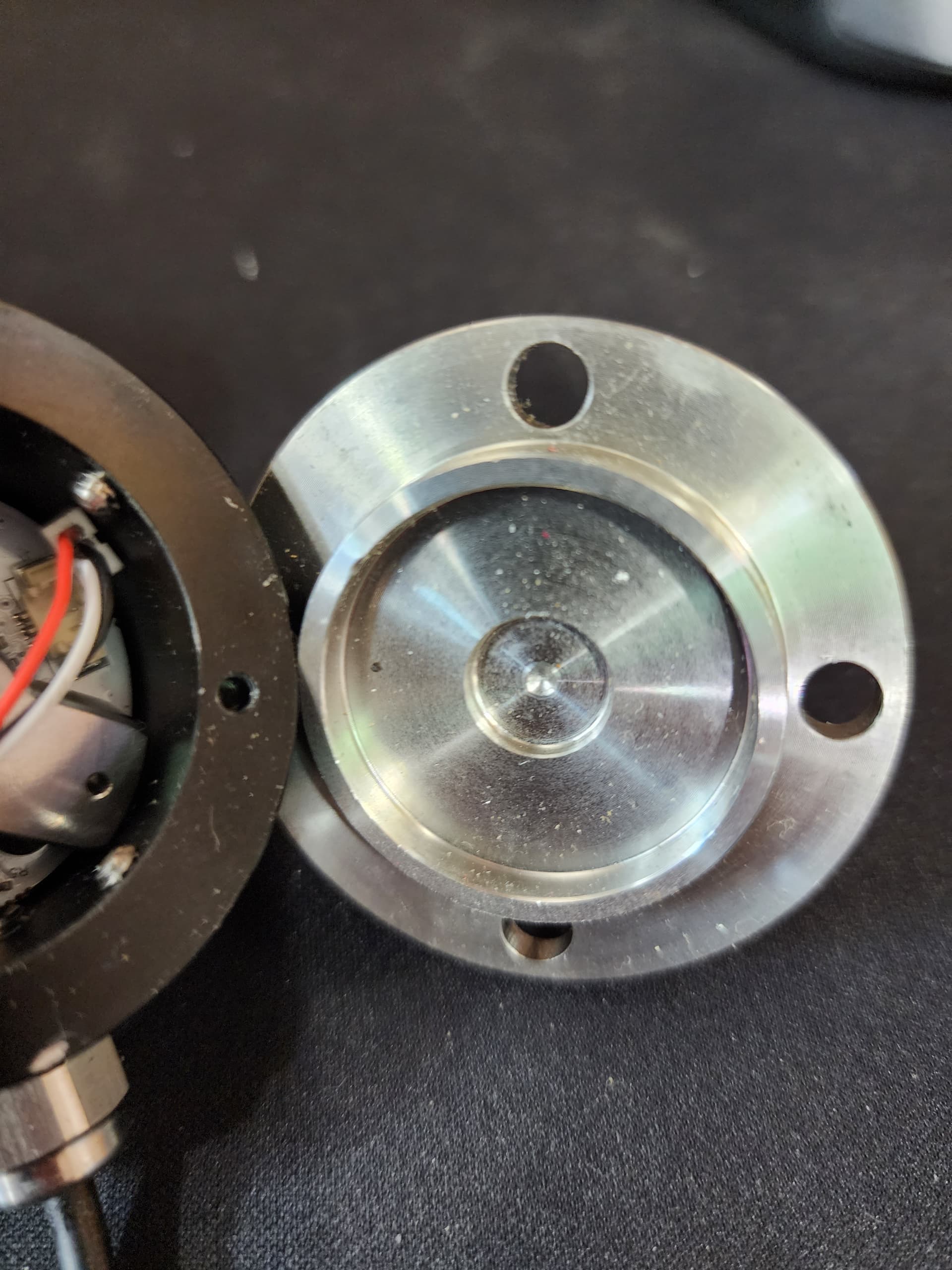
The set screws push on the boss on the top plate.
2 Likes
X and Y verified to a couple of 10th’s at 12 inches. Stacked and bolted 2 - 4 - 6 blocks checked with a height gauge on a granite surface plate.
I already had the stylus tip running concentric to a couple 10th’s. I did disassemble the probe to see how it worked before I used it. Glad i did, I foound metal shavings and some long peices of bare copper floating around in there…
1 Like
I have three of them. Out of the three, only two true out. I save the other one for parts. ![]()
It is a long frustrating process to dial them in. Take a deep breath and continue on pal.
2 Likes
Like I said previously, the tip is running true to couple 10th’s. Its just that the results don’t match what I got with the wiggler. Maybe I can cheat it by changing the size of the tip in the software…If I can get the repeatability down to a couple of thousands I’ll be happy enough
1 Like
Have you played with the probe settings in cut control? I’m not near my machine but I believe there are some settings that you can mess with that will change 0.
No, I have not.
Here are the settings for the Touch Probe:
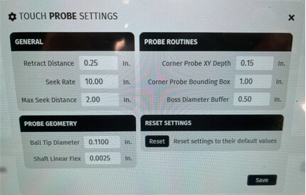
I tried to adjust the “Shaft Linear Flex”, thinking that would adjust the offset error I was seeing, but that made the offset worse. I would have had to enter a negative value to eliminate the offset error, and the program would not allow a negative value. In the end, I changed the “Ball Tip Diameter”. That change brought me within .0005 of the wiggler in X and Y. I still have to test, and verify the ball tip diameter has no effect on Z probing (it shouldn’t).
2 Likes
Nice glad that worked.
I have not tried with the latest software release but I found the same thing with my early testing and let Langmuir know. I believe they have the flex correction backwards. I ended up changing the ruby size like you did, but that is not ideal when working in tight places.
1 Like
I agree…that setting is backwards.
I see this is an older thread, but has this issue been corrected in cut control?
I have a part that requires flipping and then resetting the origin off off cuts made in the previous position.
No matter how many times I perform the bore probing routine until I’m satisfied that the origin doesn’t change after each routine, basically running the routine over and over in order to find what it thinks is true center and the final results stop changing, (using g55 to record previous xy zeros) the final part (after cutting the 2nd side) is a good 0.020" off in the y axis.
You would think that the size of the probe tip or the flex inputs wouldn’t even matter when bore probing a concentric hole.
That led me to suspect that the concentricity on the ruby ball is off. Double checking that and the needle on the dial indicator barely moves. Without graduation lines, I’d guess 0.0001" - 0.00015".
I have gotten into the routine of always pointing the nut where the wire exits the touch probe to the left or the 9 o’clock position. So, in my mind, the only other culprit would be the inherent physical limitations of the internal mechancal (for lack of a better word) tripod that is breaking continuity when the touch probe encounters a surface.
Is it possible for a 3 pronged component to accurately break continuity at the exact same angle every time in 360° of rotation? In my mind, that’s a tall order to base accuracy on. But maybe I’m wrong and will listen to logical counterpoints to my theory.
I’ve sort of jumped into cnc’ing at the deep end, and as I’m learning the hard way the limitations of this machine, some of the issues that I’ve been encountering can very well be explained as inaccurate touch probe routines. Which led me to find discussions on this very subject.
In the mean time, I’m going to put my theory to the test and see how the origin changes when I rotate the touch probe 120° vs 90° increments to see what the results are.
Any advice and/or experience on this problem is definitely welcomed. I’m kind of hoping that all my issues can be solved by dialing in the touch probe.
Thanks
1 Like
Have you updated your probe to the V2 version?
Have you updated Cut control to the latest version?
These updates have fixed the issue for the most part for me.
1 Like
Now, the new version of the probe will not work correctly without downloading 24.1.1.
And visa versa. At least to my knowledge. I have zero problems with this machine. I don’t know why all these problems are coming up.
1 Like
That is promising! I just checked and I’m running 22.1.1.
As for the probe version, it is the v2. I’ve only had the MR1 for a few months…
Let me download 24.1.1 and see if that solves my issue… I don’t want to get my hopes up. But this is promising.
1 Like
You may want to go to their website. I saved it to Google Drive. I would feel better if you get it loaded from Langmuir. Please let us know if you are good ![]()
I updated it and running the part again to see the results.
Before the update, sure enough the touch prope was 19 thou off in y after rotating it 180°.
Preliminary tests show that I’m 0.0005 off when running the same test with 24.1.1. In my mind that’s more than acceptable.
Fingers crossed…
2 Likes