While waiting on concrete to dry and extra epoxy to arrive, I thought I would do a write-up of the build so far, and document some of the mods I have made to the machine, and share my experience with the MR-1.
I work for a medical device manufacturer, and intend to use the MR-1 to make prototypes of new production equipment, and small repair/maintenance tasks. Very low volume of parts, but some tight tolerances here and there.
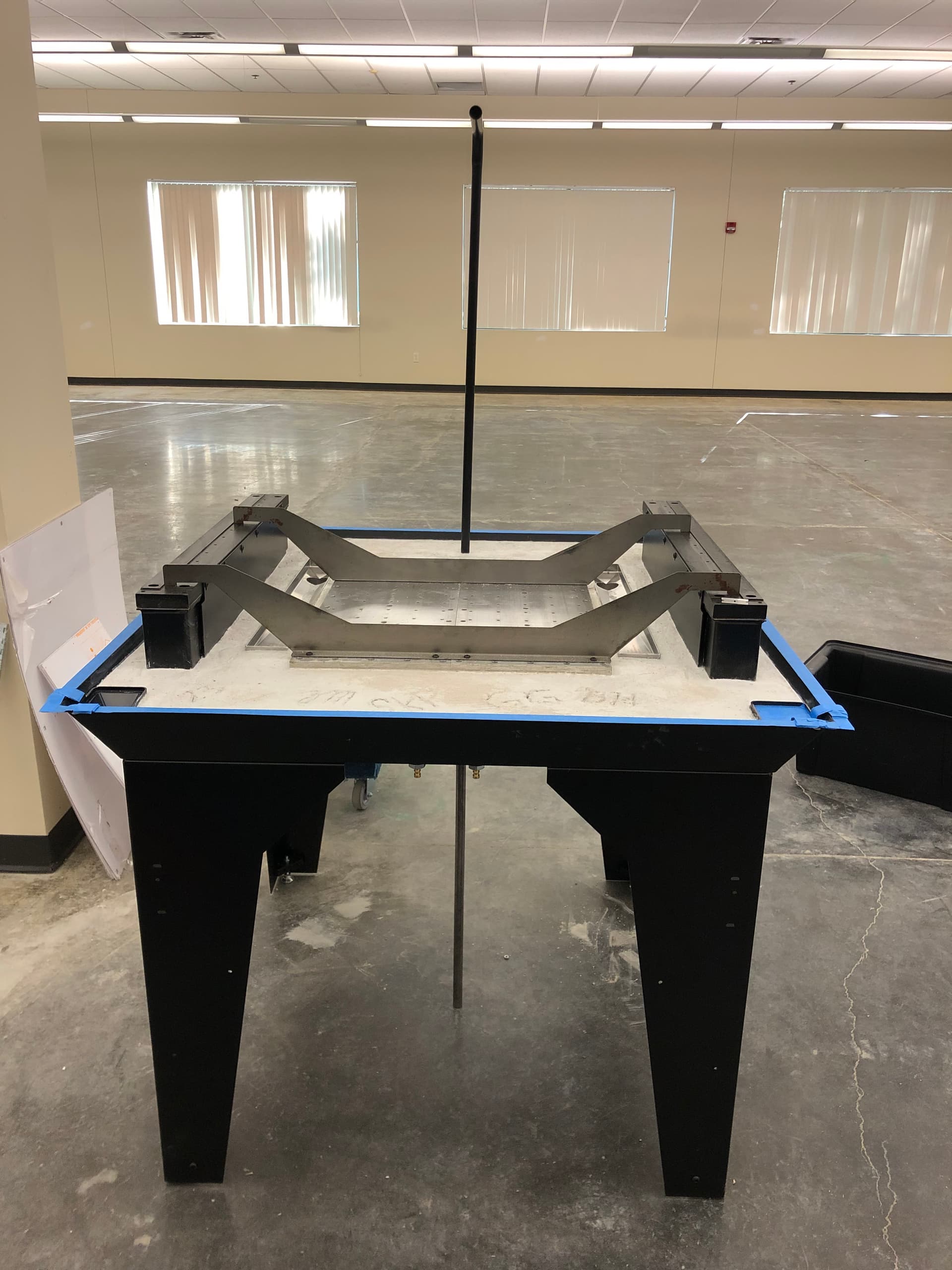
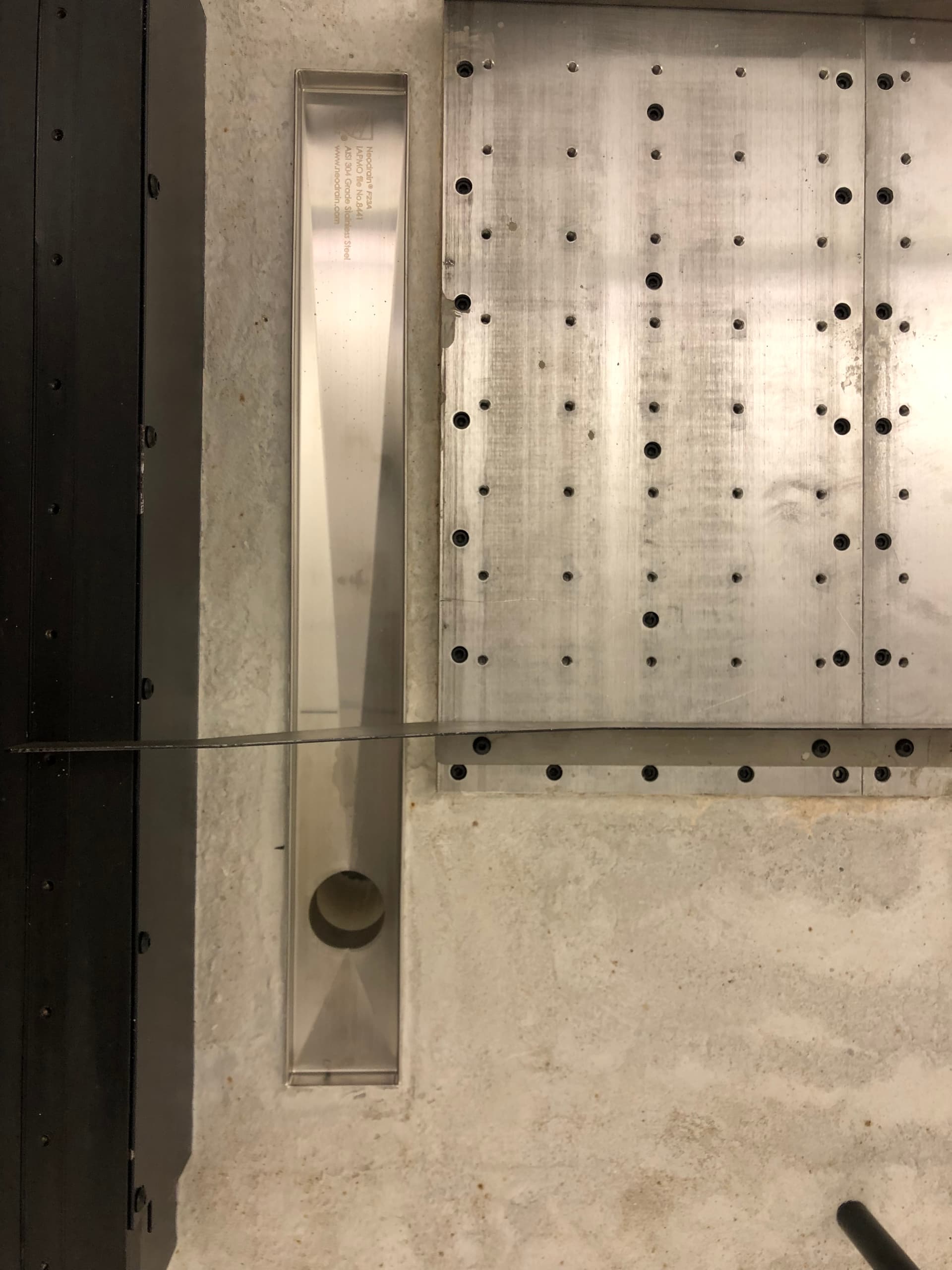
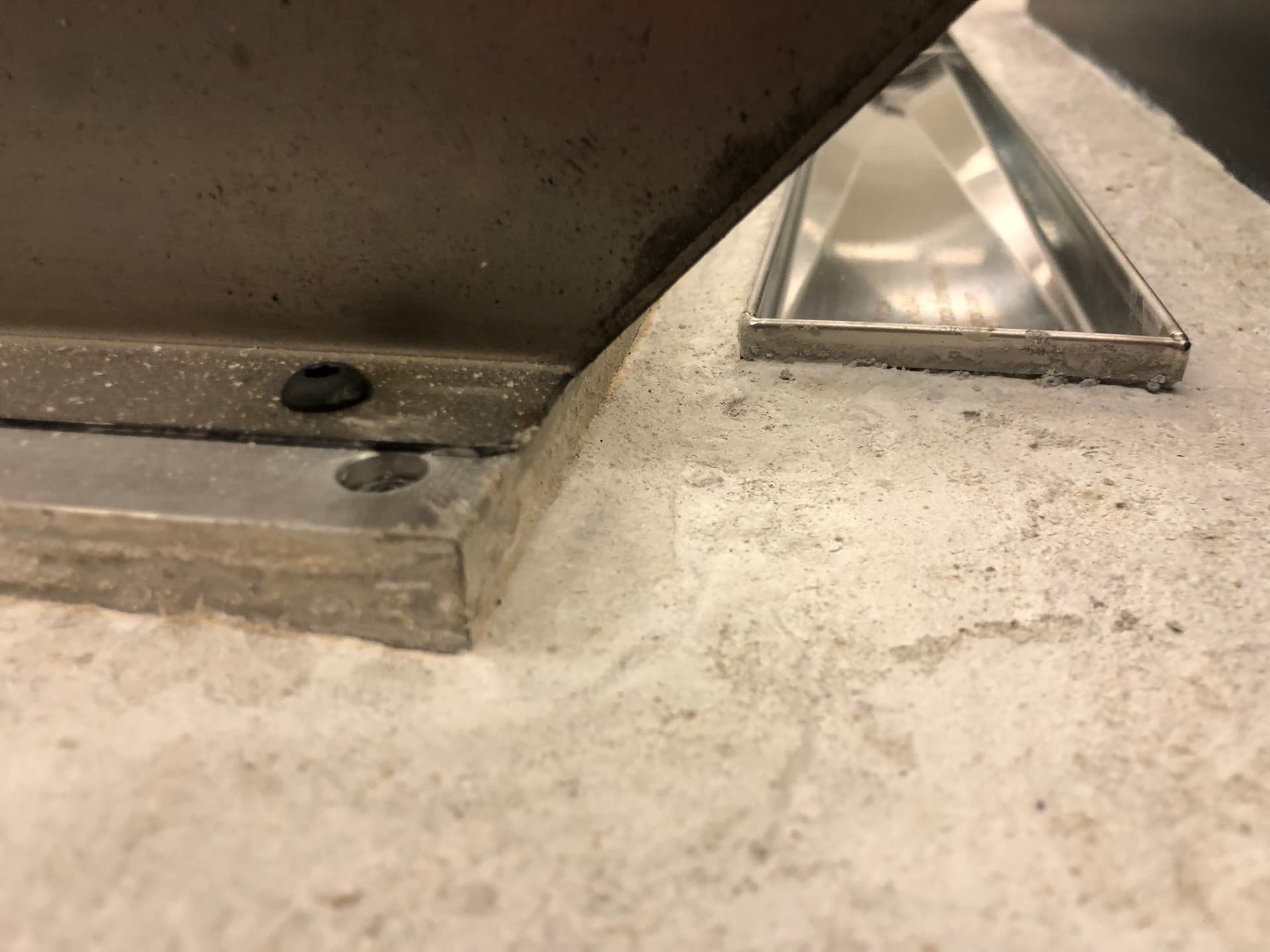
So far, we have the legs and base assembled, and the concrete poured. I added some linear drains I purchased from amazon, and used a rubber fernco coupling with silicone to seal the drain and couple it to the pvc piping. I apologize for not taking pictures before pouring concrete; I had not intended to document this process at first.
This coupling was too tall off the shelf, so I used a razor blade to cut about 1/4" from both top and bottom of the rubber coupling, and used a level and measuring tape to make keep my drain level to the corner drains as best as I could.
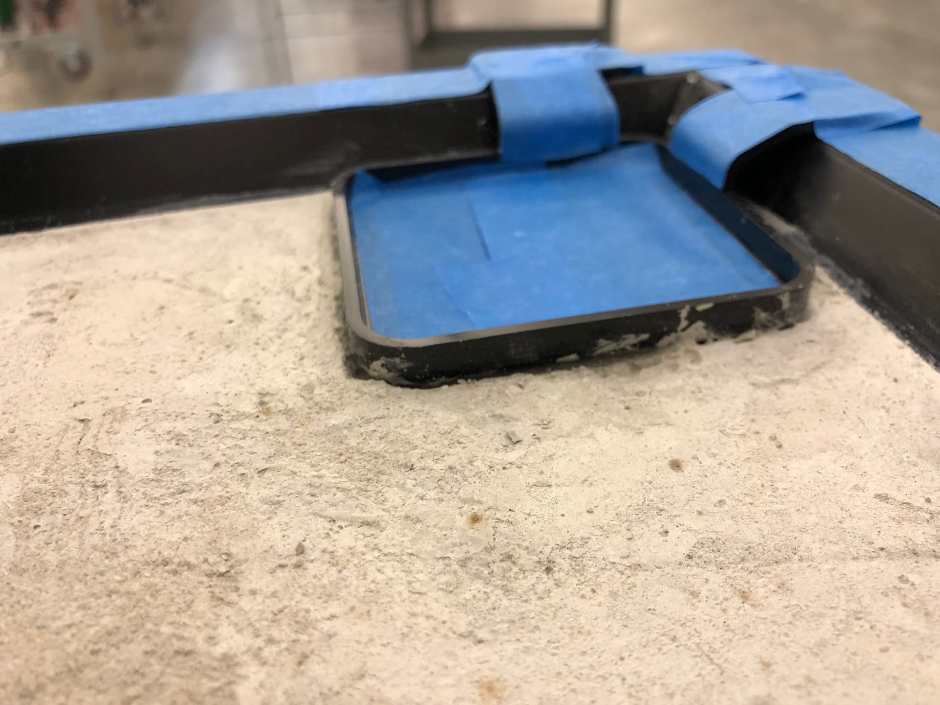
We rented a small mixer to handle the concrete, and ended up with a mix that was too watery in the end. The watery mix caused more shrinkage than was optimal, but I have ordered some extra resin, and think it should be just fine as it didnt shrink below the bottom edge of the table.
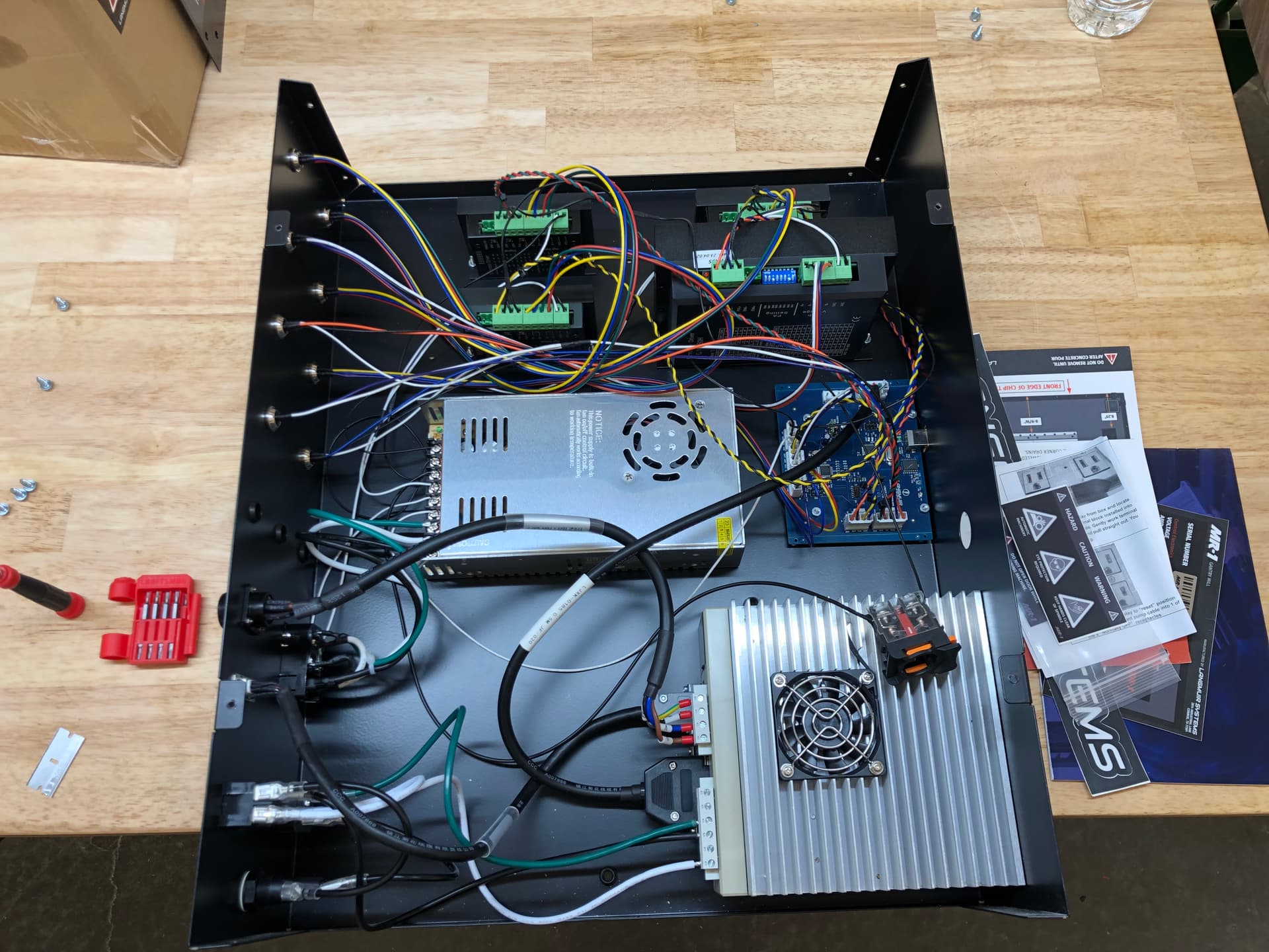
While waiting on the extra resin, I am installing high-powered drivers on both x and y, and relocating the e-stop. It was very lazy design to include such a useless e-stop. If you can’t reach it easily, it is useless.
It looks like there are some cheaper drivers available that would be suitable, but Langmuir’s model has a fan, while the aliexpress one does not, and I like cooling fans, so Langmuir it is. Might be wise to have the fans if im running a ball end mill for hours doing some odd shapes.
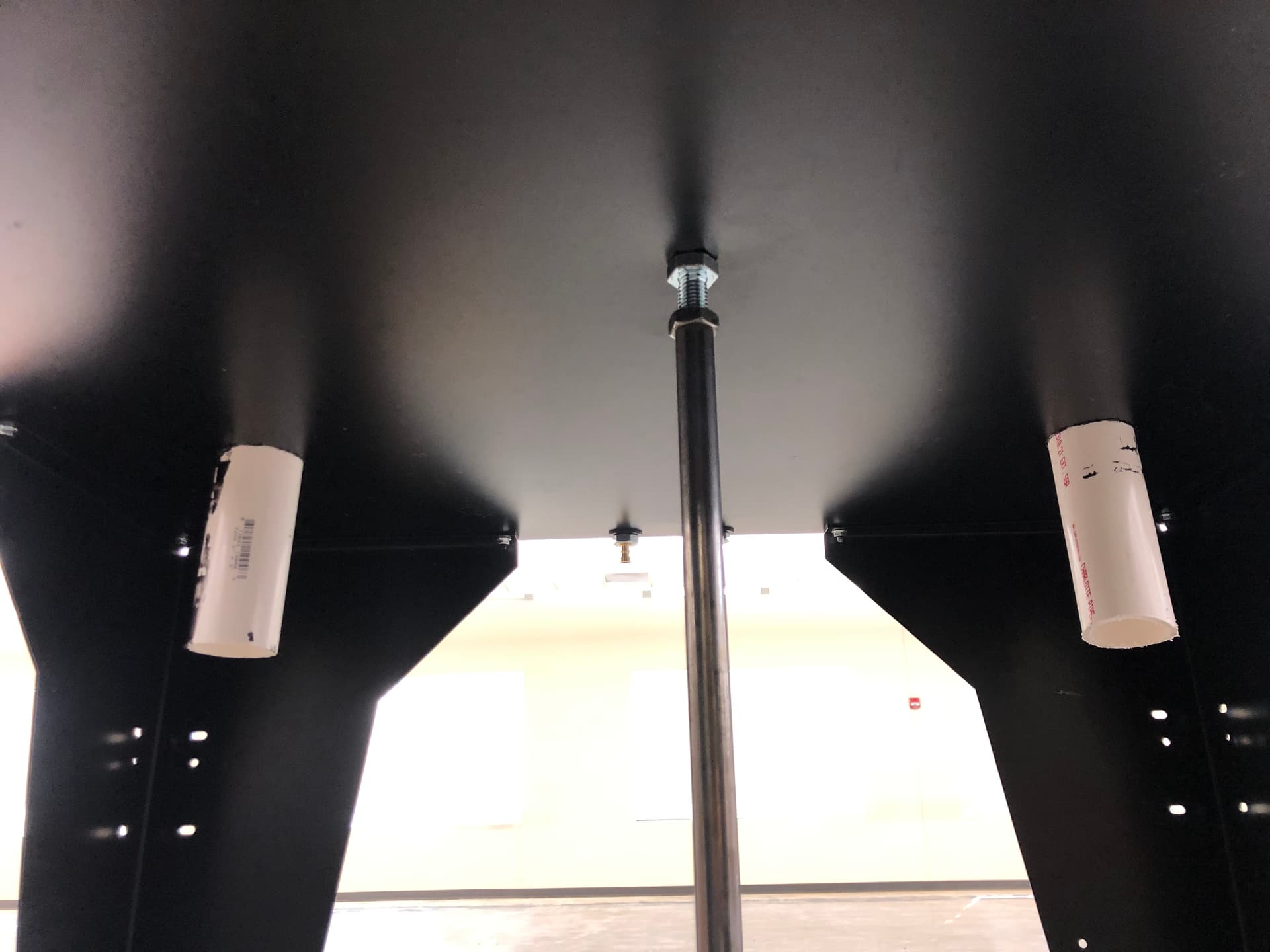
Here is a picture of the pvc coming out the bottom of the base. I made the holes for the pvc pipes in the base by using a carbide-tipped hole saw from Lowes.
Langmuir’s drivers need a fan because they don’t reduce power at idle, and are always running at full power. I got much better results switching to Leadshine drivers (I’m using EM542S, but there are many suitable models).
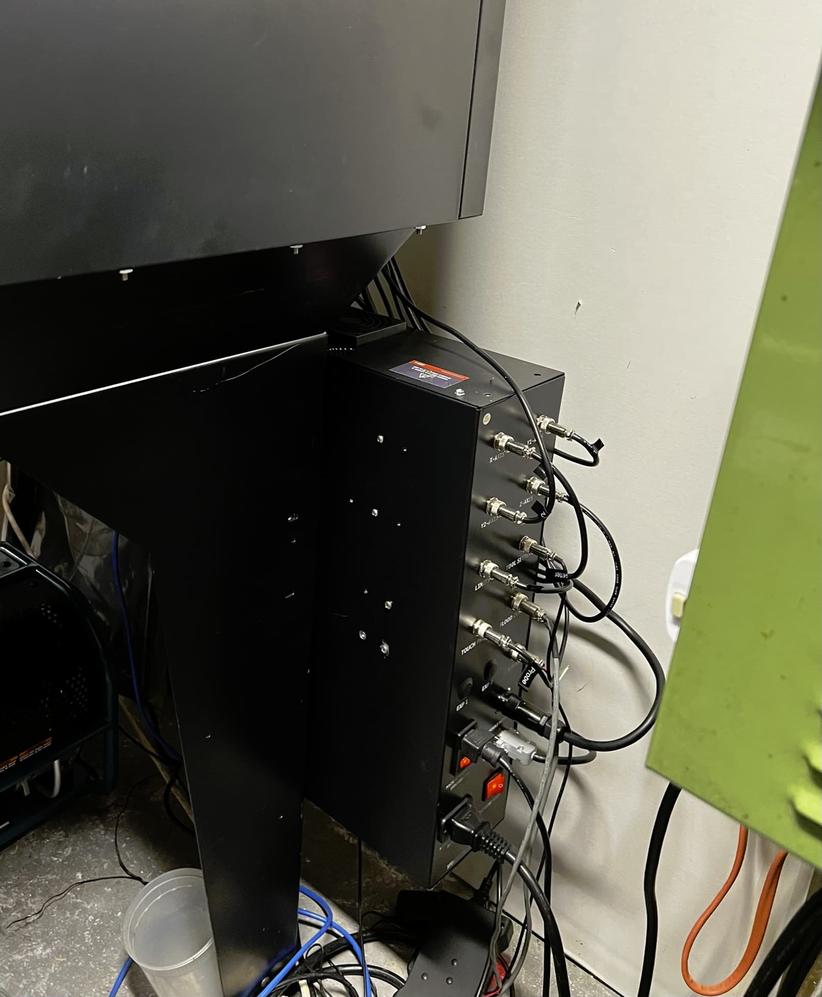
One other mod that I made was adding an 80mm 24V exhaust fan to the top of the enclosure (for the stock electronics you will need to get a 36V->24V buck converter). The stock enclosure design is sort of a heat trap since it only has vents at the bottom near the servo drive. You can see the fan’s location here, and note the fan filter to keep chips from falling into the machine:
Will update with pictures soon. Having a bad time trying to get the spindle trammed in. I followed directions to the letter but was out .011" over 3" in the nod. What a pain this has been. There do not appear to be any videos from Langmuir about how to do this step, and the “Inspecting Z-axis Alignment” video they did release is not very thorough. The presenter shows how to measure the error, but nothing about how to do the fixing. Do I take the spindle off? Do I move the bearings out and the back?
Order this. Observe one dial, flip it 180, and read the dial from the other side (which is now on the side where the first dial was observed).
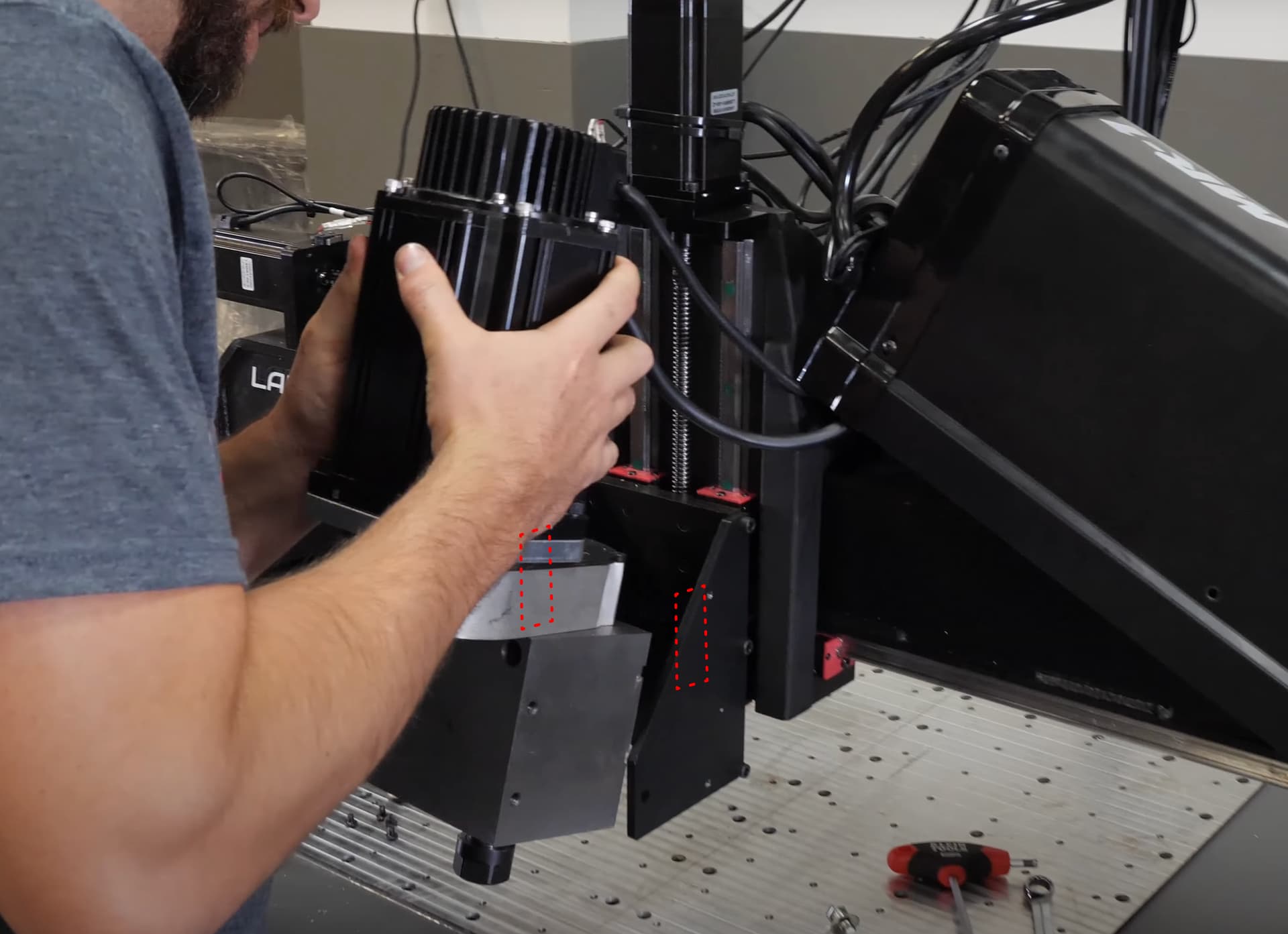
To tram nod, add shims to adjust the angle. To tram tilt, crack loose the bolts and tilt it (some polite taps with a hammer are usually warranted) and then retighten the bolts. It’s an iterative process and it takes a lot of patience.
I went to the site and was going to buy this, plus a couple of other products, but then on checkout, I was offered the option to “Add tip”. May just be getting too old and set in my ways, but I’m over everyone on earth asking for a tip for EVERYTHING. Put a bad taste in my mouth and I cancelled the checkout. Companies need to come back to reality. I expect something like this from certain companies/people (although I don’t patronize those either), but from a tool maker servicing folks that work for a living day in and day out, it’s quite off-putting. I’ll step off my soap-box now and get back to milling
Damn that does grind my gears too. Every single thing tries it these days but a tip on a tool site is extra out of line to me. If it isn’t that it’s the “please pay our taxes for us” disguised as “please donate to St. Someoneoranother.” I can’t stand it. Anyways, yeah, back to milling.
Thankfully I already have a nice indicator and arm for it. Mostly I was just frustrated at having so much error in the first place, after using the shim calc and such. (Which others say is not reliable).
Thank you for the tool suggestion!
When you say angle, you mean the 4x bearing surfaces, yeah? Can I crack loose the two bearings at the top to remove excess shims without putting too much weight on the bottom two?
Here is the video for adjusting the nod. It’s pretty straightforward.
To adjust tilt I put shims between the side of the spindle block and mount. As you tighten the bolts in from the backside, the shims should prevent it from pulling out of tilt. It was hacky, but I couldn’t stand having my tilt 0.003"/1" out of tilt as it arrived. I’d love to hear alternate suggestions.