My Crossfire Pro Evolution

This is a place for me to log all of the various modifications I make to my Crossfire Pro in one spot. I’ve found it can be useful for me, and potentially others as a repository where one can go and see what was done, and how it has held up, or needed to be redone over time.

For those that didn’t read my intro thread, I’m a manufacturing engineer, with a majority of my work experience related to CNC tube and sheet metal fabrication. In particular tube and sheet bending, rolling, and laser cutting.

I’m at a different point in my life now where I work as an on call engineer for a manufacturing company here in Lincoln NE, do a lot of house dad work, and spend the rest of my time designing or making things as much as possible. I’ve always said my hobby is trying out hobbies, and I’m damn good at it. :sweat_smile:

Long story short I’ve built up a decent collection of modest equipment and after a rough year with my family and 3 other family members households moving and all the chaos that ensues from that, I’m finally back to the point where my tools are organized enough to start working on serious projects again.

Equipment list as of 2-1-2021:

  • 1981 Enco Round column manual mill

  • 1980 Enco 10x20 metal lathe (in need of 2 feed gears repaired from high school duty/crashes before I got it)

  • IH CNC mill (in need of Y axis ball nut adjustment)

  • Lincoln Electric 175HD MIG welder with gas setup

  • HTP Invertig 221H DV, with water chiller

  • Primeweld Cut60 Plasma Cutter

  • Coleman Powermate 60 gallon air compressor (currently building copper pipe run to start dropping moisture, then Max Dry XXL air dryer system, then Motorguard filter just before plasma cutter)

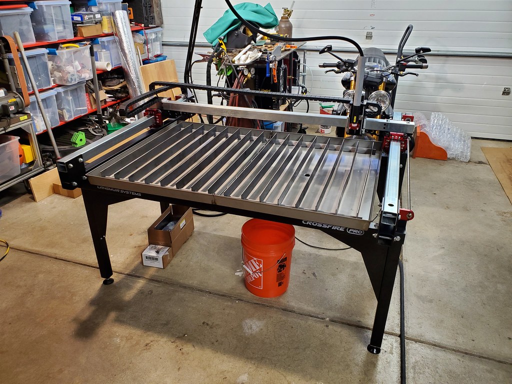
  • Langmuir Crossfire Pro w/THC

  • Lulzbot Taz 5 3D printer (I have a Wham Bam build plate system and E3d Titan Aero Extruder to install to bring it up to date with 5 years of 3D printer evolution)

  • Variety of woodworking and grinding equipment

As much as possible I will try to update post numbers to make finding relevant information easy.

Posts to follow:
Drag chain upgrade
Water Table Upgrades
PTM60 Machine Torch for Cut60
Computer
36V power supply repair/replacement
Welding curtain system

2 Likes

Drag chains:

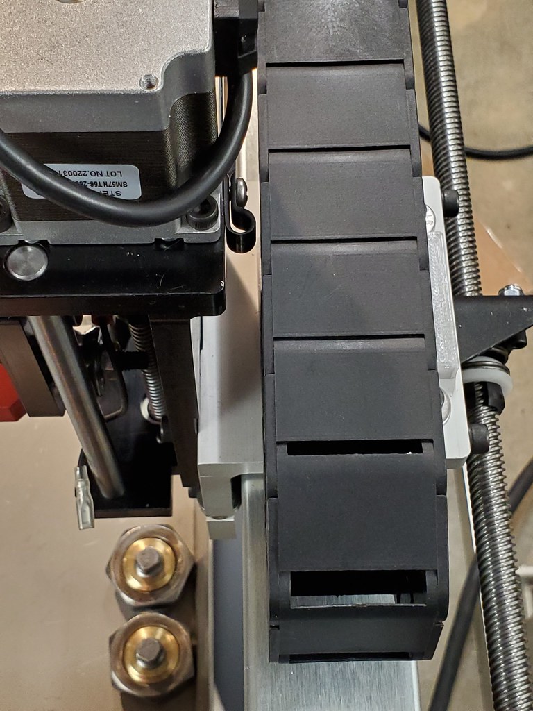
2/1/2021 - I started this project thanks to the great DIY from @felich. I ordered a slightly larger set of drag chains than he did, as I saw the potential to want to run other cables and wires as needed for future upgrades. I used 15x30 (Amazon link, I am not an affiliate or anything) drag chains that have a mostly closed back side but can be opened from the inside and easy snapped apart and together for whatever length is needed. See the post felich made for a great DIY.

I decided I wanted my XY mount to attach differently, and everything needed to fit my drag chains so I modeled new mounts.

The drag chains attach to the mounts with M3 screws into heat set brass inserts I got on Amazon. The mounts attach to the machine either through OEM bolts, M3 screws through the tube into brass inserts, or through the mount into 1/4-20 rivet nuts I inserted in the tubes. My goal was zero impact on axis travel.

The filament is a discontinued nylon called BluPrint from Taulman. It has higher than usual UV and heat resistance and I felt it would be a good candidate for parts on a plasma table.

X carriage mount.

XY axis mount

Table side:

XY axis mount and Y axis mount

Overview during assembly

Overview after final assembly

2 Likes

Water Table Upgrades:

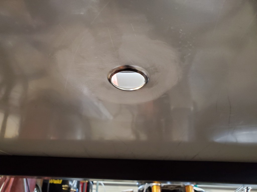
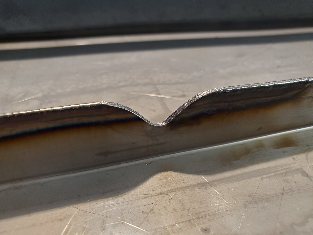
2/1/2021 - I TIG welded in drains, and my pan halves together. I took lots of time and never welded more than about 4-5" per side of the seam working in symmetric lines before giving the pan time to come back down to ambient temp. I only welded the edge side, sweat welded the two halves together at around 80-100A I’d guess based on where I had the pedal and a set max of 120A. I’m not worried about it pulling apart as it will likely never leave the frame unless its to be upgraded in the (maybe/probably never) future to a 4x4 table.

I used 308L rod for the drains, and can’t remember what electrode, edge seam was just a sweat weld between the two pieces.

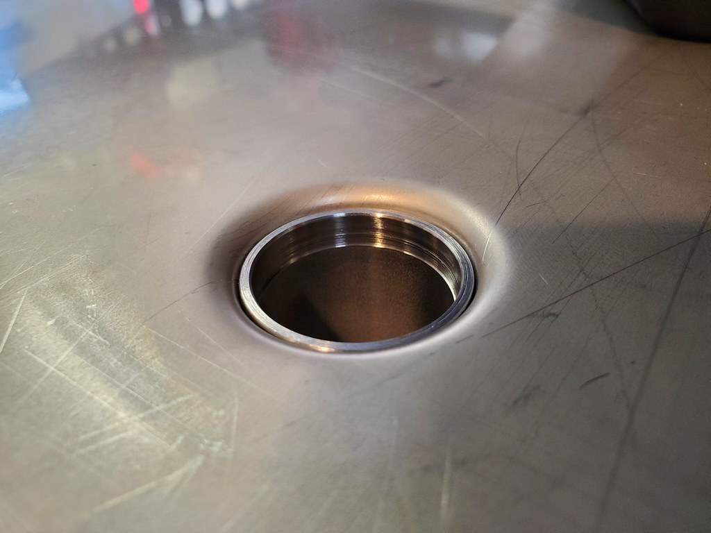
The punch and die I used to create the flange in the drain were turned on my lathe. The punch is a piece of aluminum, and the die is a piece of 304 hex stock scrap. I used a fine thread 1/2-20 grade 8 bolt to draw them together

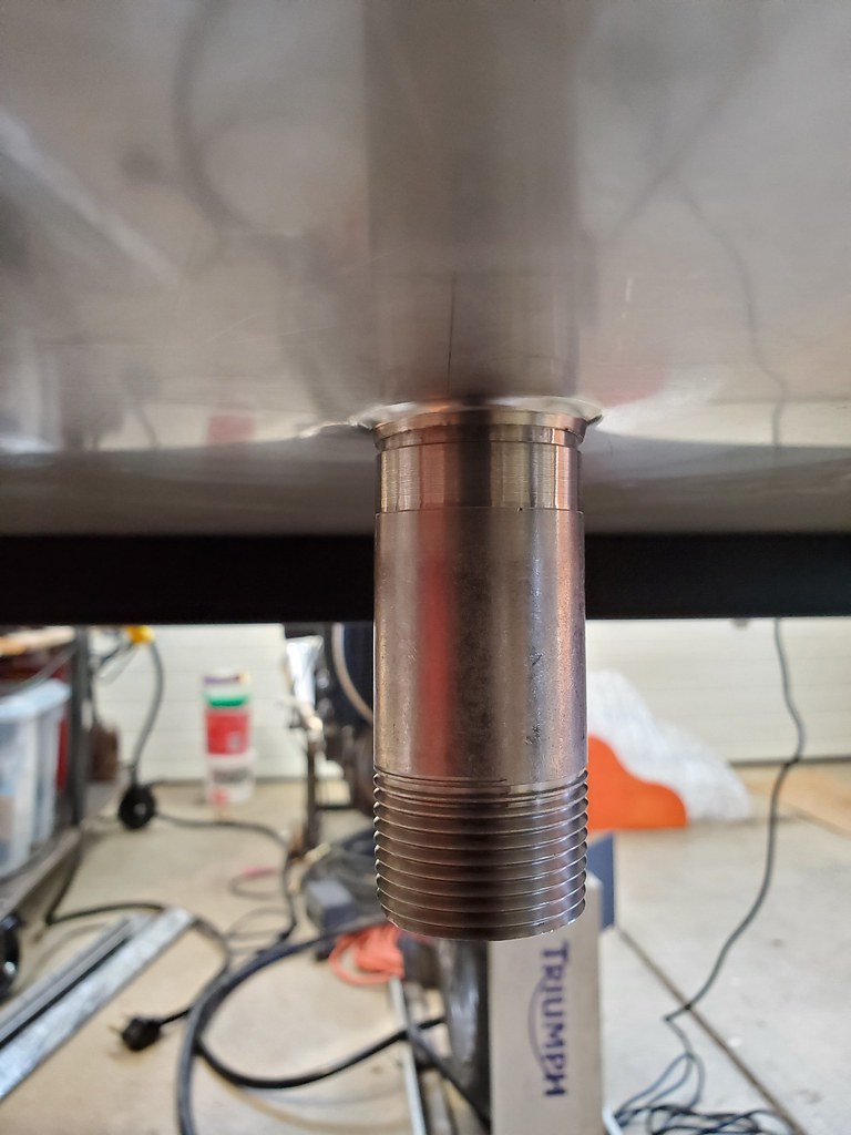
The drains I made from a 304 stainless 1" NPT pipe nipple 6" long that I got from a supplier in town called Kelly Supply. I turned it on my lathe and split it into 2 equal parts and turned it down to be a press fit into the flanged drain edge so I didn’t have to futz around with holding it in place when I went to weld it.

After the drain I put 2 1" 304 ball valves, and once I have some 1" hose and a tank I’ll add my 90° fittings, barbs, and barbed brass tee.

The drain sits below flush so that after welding there is no lip for water to get over.

I used the bolts to hold the pan halves together till I had it tacked everywhere I wanted it, then vee’d out the slots with a carbide burr so I had plenty of room to work the tungsten. I made sure not to use any abrasives or chemicals that might contaminate the welds in the V sections, thus the carbide burr.

Cleaned up with a scotchbrite pad

This is before I went back over the OEM corner seam and made sure it was solid as well.

I’m no pro welder, so I was mildly nervous when I went to water test it, but it has no leaks from anywhere, and I filled far higher than I ever would in use. So I did a good enough job.

It even does a decent job draining, this is all the water that’s left after it finishes.

Future concerns about such a modification:

Will the plasma cutter be able to notch the welds on the edge seam over time and cause them to become spotted with holes?

Will corrosion become a problem over time due to the welds, or the living conditions they’re exposed to?

2/17/2021 - I finished off the drain lines for the table. This included connecting the left drain to a 1/6hp sump pump outlet to use as a table fill pump. It takes 90 seconds to fill the table with the filters in place, and 70 without.

I didn’t want to rely on a water tight container and air pressure to fill the table, it just feels like one of those recipes for disaster with electricity involved close by. Drain time is about 8 minutes with the filters in place. The filters are just pieces of scotch Brite pads rolled up and pushed into the 3" worth of tube before the ball valve, and a flat piece over top of that to hold it in place and provide a bit of extra filtering.

I’ve got the pump and a Bucket Head vacuum set up on waterproof switches so I can turn them on and off at will. Each line is fused in the switchbox and the box is fully isolated front the machine frame.

3 Likes

PTM 60 Machine Torch:

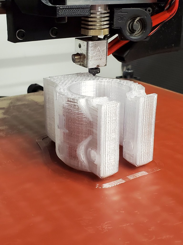
2/1/2021 - Printing right now.

For those interested in making their own mounts, if you want it to line up with the PT60 hand torch mounted in the anodized red aluminum mount provided by Langmuir, you are aiming for approximately a 41.5-41.75mm centerline from the face of the mounting plate (not the recessed slot) to the center of the nozzle. The PTM60 torch is approximately 35mm in diameter. Its a little smaller in the black plastic area than the grey protective tube.

The slot is approximately 1.5mm deep and 25mm wide, the mounting plate is 80mm X 80mm, and the bolts that mount the steel strap the hold the mount in place are on the centerline (40mm up or down depending on how you look at it). The strap is 20mm tall, and about 2.8mm thick. Plan to swap out the right side knurled hand tightened bolt for a regular SHCS so you have enough clearance to the mount.

2/3/2021 - Houston, we have a problem.

I think if I would have printed 100% solid it would have resisted this, but the potential failure mode I was concerned about, ended up being the failure mode. I find it interesting that it traveled across multiple layers, so it appears that for the most part there weren’t layer adhesion issues.

Revision 2 is going to use the original aluminum holder, and just be a stabilizing mechanism at the top so that most of the force trying to peel the torch away from the mount is controlled and distributed to the aluminum which is far more capable of handling the load. Ironically, had I not worried about trying to maintain fast swappability with the original hand torch mount, I could have just bolted my torch mount to the mounting plate and avoided weakening it to make it use the original scheme of sliding and being clamped by the steel strap. Maybe I should still go this route over using the aluminum mount, but I do want this to be a quick connect sort of tool head.

I’ll ruminate on the long term solution after I print a short term one to get me going, once the new power supply comes in that is.

2/6/2021 - New PTM60 torch mount is complete and a vast improvement over trying to make something off my printer to work with Langmuirs mount design. Since I’m not afraid to twist 2 screws a turn each, I decided to use a keyhole slot mount. I’ve found on other things that this is a quite durable and quick to use mount style for 3D printed parts. It’s not tool free, but honestly I’ll trade reliability for tool free any day.

I printed it in PLA on the assumption of 2 things:

  1. I’ve designed it to keep the fire-breathing end of the torch a good distance away from the mount. It should take quite a while for heat to creep far enough up the torch to seriously degrade the mount in a hurry.

  2. This is not a final design, but a good place to start. I expect I will refine the design and make accessories for it that given enough time will make it worth reprinting the mount with some of the accessories integrated into the design.

So, here’s where we’re at, a PLA torch mount that uses button cap screws to mount through keyholes.

Extra long M6 bolts tighten the torch in place by going through brass heat set inserts to provide the clamping action. The nuts lock the bolt in place, and allow an easy mounting point for accessories. I also have 4 M3 brass inserts on the upper and lower face on a 50mmx50mmx25mm spacing to give me lots of options for where to mount other things.

My confidence in the rigidity and long term durability of this design is much higher than the previous. A good reminder to save the fancy filament for a final design.

1 Like

Computer System:

Computer: Beelink U57 Mini PC: Intel Core i5-5257u Processor(up to 3.10 GHz), Windows 10 Pro, 8G DDR3L, 256G SSD

Monitor : Asus Zenscreen Touch MB16AMT: 15.6" Touchscreen

Setup:

The setup of the computer and monitor were mostly straightforward. I did end up having to install the THC drivers manually despite the fact that Windows 10 is supposed to find the correct ones automatically. I also found out that the only way to have the touchscreen functionality work was to use the USB-C to USB-A adapter that Asus includes, and install their drivers package. I should specify that maybe it would have worked without the driver package, but I had already installed them by the time I broke down and tried the adapter.

After that everything seems to be working fine. I installed Fusion 360 on it, but we’ll see how well it runs if I actually end up having to put it to work. First impression was that it was a bit laggy on occasion. Firecontrol is snappy and works great, though for whatever reason the feed rate override doesn’t appear to work. That could be a problem, in my experience that’s one of the most useful basic functions on a day to day basis using CNC equipment.

feed rate override works, but doesn’t modify rapid speeds, which is not what I’m used to

36V Power Supply:

2/1/2021 - Waiting for an email response from Langmuir support about what appears to be a power supply that is DOA. Does not power on when plugged in and switched on, but Firecontrol connects to the Crossfire board, which is powered off the USB.

2/1/2021 - First reply to my email regarding power supply 19hrs after initial email Sunday night. This is nice and quick, no complaints about the promptness of their reply. They asked me to verify the 110v/220v switch position and whether the light turns on on the power switch when turned on. Yes to light turning on, and power supply being set to 110v. I replied 10 minutes after receiving their email.

2/1/2021 - second email came 70 minutes after my reply. They asked for me to check for loose wires and take a picture of the power supply wiring for them. I sent 3 pictures showing the power supply wiring, an overview of the whole case interior, and one showing the power light on with no light on the power supply about an hour and a half after their email.

One more email came in 4 minutes later telling me they would get me a new power supply shipped asap.

Total time to resolve issue from first contact: about 20 hours
Total time of normal business hours: 7

I’m pleased as could be with the resolution time, I’m looking forward to receiving the new power supply so I can test out my new machine.

2/4/2021 - New power supply arrived today and I got it swapped out. Everything is up and running. I went though a number of break in program cycles, and ran the THC test with no issues besides stepper motors that are making a faint high pitched noise that makes me want to put ear plugs in. More about that in a coming post.

2 Likes

Following thread! - Looks great!

:+1:

1 Like

Not sure who all might be experiencing this, but at certain (most) times when the motors are stopped I’m getting some high frequency oscillating noise. It’s not always the same pitch or volume, and sometimes the machine stops and is silent.

Here’s a waterfall audio graph of the machine off. Some ambient noise from my heater is all.

And this is with the machine on.

The frequency is peaking around 12.5kHz, would that happen to correlate to the stepper pulse frequency? It’s loud enough to be very grating, but quiet enough that anyone with early hearing loss might miss it.

Welding Curtain System:

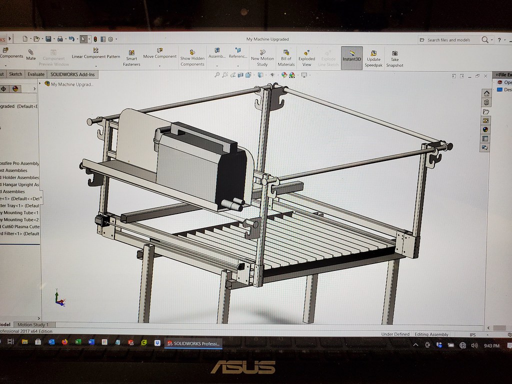
2/17/2021 - I keep tinkering around with upgrades to the machine. I’m in the process of designing a welding curtain system to manage sparks and splashing, and a plasma cutter tray to keep it close enough to the machine controller. I’ll mount the Motorguard filter there while I’m at it and make it big enough to be a tool tray too. The cords for the THC and trigger come in too short to do anything but put the machine above or below the table, so it kind of forces my hand if I don’t want it below the table. It’d be nice if they were a little/lot longer.

1 Like

They are just standard 5.5mmx2.1mm cords, for which you can find plenty on amazon, either replacement or extension cables. Look for ones with higher gauge wires.

1 Like

Absolutely beautiful build. Your curtain idea look great! I’m going to copy that!

I think the steppers making noise at idle is normal. It’s been talked about here before somewhere, and mine have the same noise you’re describing.

@brownfox

I bought 6x6 curtains off of Amazon. They are the red version of the Tillman brand. I plan to cut 2 curtains in half to get 4 6x3 curtains. I wanted them to be easy on and off for loading material and maintenance.

1 Like

I bought a couple of 25’ barrel jack cable extensions. If I’m going to have line noise issues from using longer cables, these should make it show up.

Yes, Idle current and the stay locked-up, very slight buzz …all normal

A slight buzz I wouldn’t worry about, it was a very high pitched noise, but muted and high pitched enough to just make you think you had a mosquito cussing in your ear canal. I had to really make an effort to pinpoint it to the motors. I’m familiar with the growl that steppers sometimes make, this isn’t that.

It’s been a few days since I fired it up and moved it, I’ll have to see if it’s still doing it.

Looks great, nice job on the welds. What alloy fuller rod did you use on the pan?

I used 308L on the drain and didn’t use any filler on the seam.

How many amps did you run on the seams and did you do anything to help to keep the pans from warping?

I TIG but I’m not all that good at it. Usually takes me a while to find my settings.

I believe I ran about 100 amps pulsed at 50% duty (approx 1 on pulse and 1 off pulse per second), but I almost never had to use full pedal. If I had to guess, my average was around 65-85A during the on pulses.

Take your time. I did about 2-3" of weld on opposite sides of the seam and then let it cool to ambient before doing another 2-3" on either side. I may have pushed this a bit a few times, and it still came out just fine. I’m using a gas lens setup on my HTP 221.

2 Likes