Is the power input to this new beast of a spindle the same 220volt 20amp? When will the web site be updated? Im concerned of the very vague information on the machine that I ordered. I have stopped working on my shop soon after my order because of this. Your Marketing is great. Your information stinks.
There’s no change to the spindle motor or drive system- so all of the wiring etc is the same, as is the power and the speed range. The only thing that is changing are the spindle shaft, spindle casing, and the spindle bearings.
7 Likes
I really appreciate the updates, thanks.
The little delay is worth the wait if it corrects a future problem. Think they bitch now that its running late but just imagine how much they would bitch a couple months into use and the machine goes down in the middle of a job. Because the problem wasnt corrected. Be patient people. This machine is filling a void in the market. They are just trying to make sure what you get is a quality product
4 Likes
The first prototype MR-1 machine was built back in 2019. The concept of the initial machine was that it would be mostly for wood cutting and some light cuts in aluminum. It was all steel and cast iron construction and was intended to be used with a 65mm trim router (think Makita, Dewalt, etc). As an upgrade option, we developed a low speed spindle that was a direct replacement for a trim router. At the time it came with about a 1/2 horsepower motor and would spin the tool to around 5000 RPM.
The trim router was basically useless on Aluminum, but the low speed spindle cut aluminum surprisingly really well and we were able to achieve MRR on Aluminum of around .75 cubic inches per minute. The Spindle worked great for those kinds of cuts…(fast forward to now and the biggest cuts we have ever taken on Aluminum are 18 MRR with a 3/8 2 flute end mill, thats when the 3.4hp spindle motor stalls).
The machine was cool and revolutionary, but we wanted more. We redesigned the machine adding more rigidity and mass. The original spindle set up was carried over. At this point in development the machine was to be exclusively a metal cutting machine. Substantial rigidity improvements were made to the system and we were seeing around .005" of spindle deflection with 50 pounds of applied. Not particularly stiff, but stiff enough to make decent cuts in aluminum.
We started dipping our toes into steel cutting with that machine and decided that with just a few changes we could get a machine that would cut steel really well. We developed another prototype adding more mass and rigidity everywhere. Is at this point that we did the first concrete base (huge leap forward!). Deflections on this machine dropped to around .0035" of spindle deflection for 50 pounds applied. By this point the same low speed spindle was significantly under powered so we put a bigger motor on it, around 1 horsepower. With this machine i think we were getting around 5 MRR on Aluminum and around .75 MRR in steel. We had to completely redesign the belt drive system and tried a wide variety of belt set ups and pulley ratios. All the while, it used the same spindle bearings and shaft as the original design.
We did yet another prototype iteration to extract as much rigidity as possible. We added the Y Axis Rail Stiffeners to tie into the concrete, increased the thickness of the Y rails to 1", went to iron castings for the X and Y carriages, increased the wall thickness of the gantry, increased the thickness of the lead screw bearing mounts to 1" steel, and added angular contact bearings thrust bearings to the drive screws on all four axes. Again the original spindle was carried over. Spindle deflections at this point were held to around .002" with 50 pounds of applied load. It became clear that the machine was power limited and had the thrust force and rigidity to make larger cuts. So we ditched the 1hp PMDC motors and went to the 3.4hp AC servo motor. With this set up we have been able to achieve 18 MRR on aluminum and 8 MRR on steel which is the very limit of the machines rigidity, its spindle power, and its linear thrust capacities. The machine is super well balanced now thanks to a lot of development spanning years.
The problem is that the original spindle shaft and bearing arrangement that was designed in the very beginning was carried all the way through development with no changes. It’s issues only became apparent when doing prolonged torture testing of production spindles doing heavy roughing of steel on the machine at substantial MRR. We found that this level of abuse was compromising the bearings to the point where surface finish and resonance problems began appearing.
There was of course a mix of opinions at the company about what to do about it, but myself and Mike Downs were very adamant that a new spindle was larger shaft and bigger bearings was needed to rectify the issue and that it was worth delaying to do it. At the end of the day the buck stops with Mike and I and we just didn’t feel comfortable putting a spindle out there with potential life span concerns.
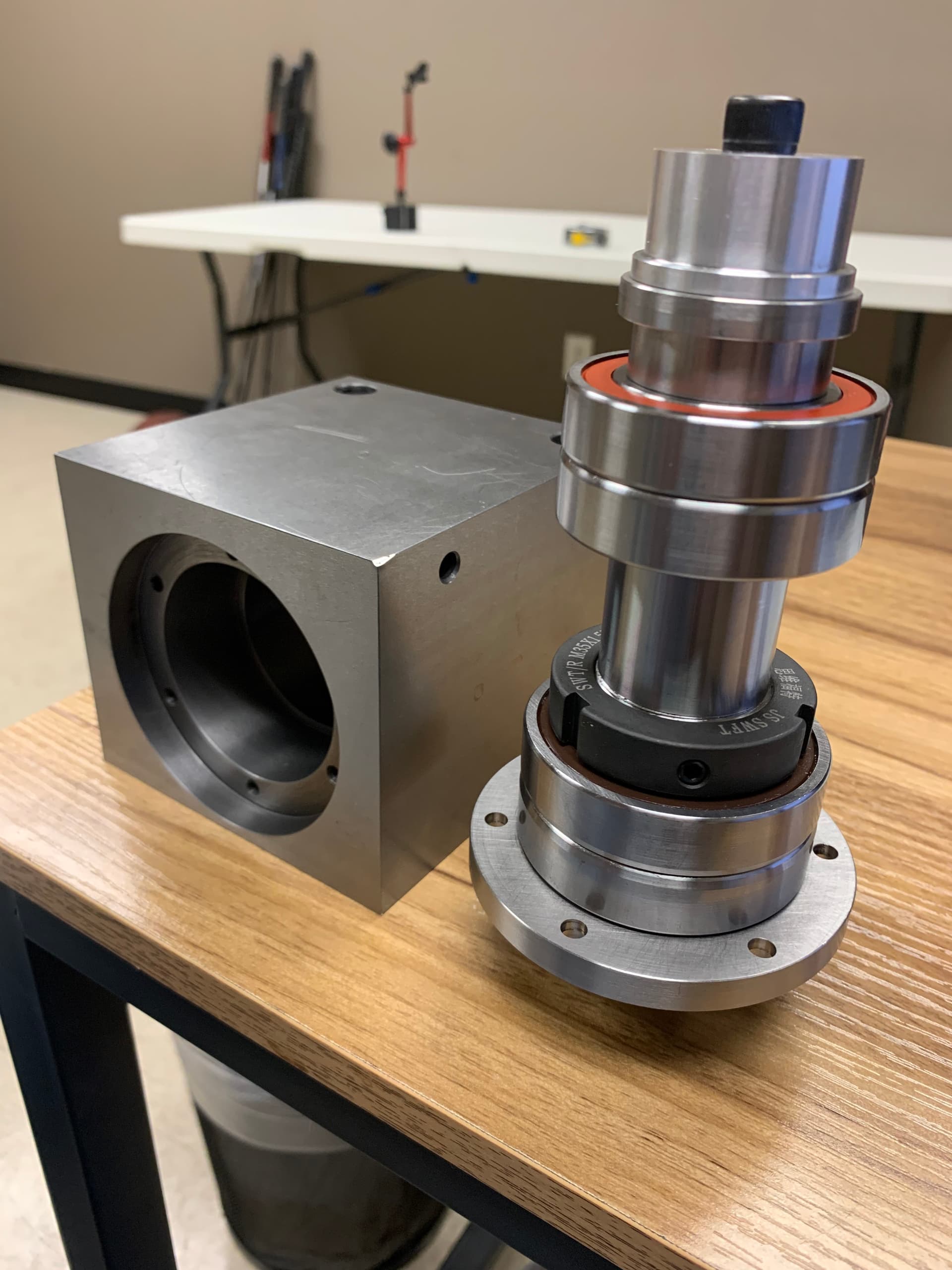
We did what we should of done a long time ago- which is to go to a cast iron spindle casing, larger shaft, and larger angular contact spindle bearings (7007 15* back-to-back at the bottom and 7006 15* back-to-back at the top). Finally the spindle assembly and bearing arrangement is evenly matched with the rest of the machine!
We built a prototype in house and have been running it the last two weeks with great results. We’ll continue torture testing that for the next 6 weeks. In parallel to that we have our spindle supplier building 10 prototype assemblies which are expected to complete at the end of this week. Still in great shape to have bulk quantity spindle assemblies in our hands in about 5 or 6 weeks.
10 Likes
It’s nice to know the back story. But why and when was the decision made to change from the prototype BT30 spindle to a solid spindle with only one size collet? Price? Somewhat. Concentricity? Maybe. But also a great loss in versatility.
Mill and Lathe Spindle Complexities

GlockCNC Headstock Bearing Guide

I modified an existing BT30 spindle shaft for prototype purposes because while I can turn the shaft seats and faces, etc, I had no way to produce AT4 taper needed which requires grinding.
There unfortunately is not enough room on the machine to incorporate BT30 tool holders for production. It’s fine for the prototype- not a viable production solution for a variety of reasons, primarily clearance. The machine would really need to be designed from scratch around the BT30 spindle and the cost difference would be quite considerable.
Many will be turned off by the lack of tool changing ability, just like many would have been turned off by the added cost of the machine if it had it. We can’t build the machine to fit everyone’s needs, but did our best to cast the widest net possible.
7 Likes
Are we just waiting for this spindle upgrade?
I want to watch cnc porn.
2 Likes
Hey ya’ll,
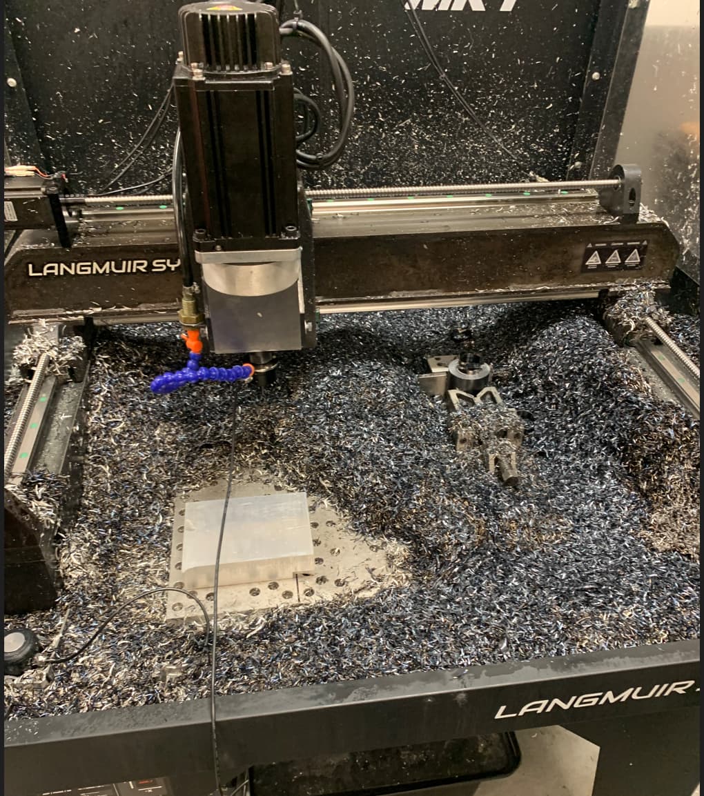
First of all want to thank all of our customers for their patience. We got in the first three production spindle assemblies earlier this week and have been testing them extensively. So far performance has been great and the bearing degradation issues we were seeing with the earlier spindle design seem to be gone.
We’ve mostly been hogging away steel on the machine just to get hours on the spindle, but hopefully we’ll get some time here soon to bring out the camera and film some more cnc goodness.
We’re still sticking to the (delayed) schedule nicely and our spindle assembly manufacturer thinks we’ll be able to get decent quantity delivered around the 2nd or 3rd week of October.
10 Likes
You made quite the mess! I guess that picture might solve some of the worries of shavings causing problems with the lead screws haha
Gotta say WOW! That spindle is a beast. Super strong and will last forever I bet.
Let people cry about a tool changer and BT30 holder , they can buy a Chinese machine with only a 9 " x 11" work area!
That is the big difference. MR-1 can mill a 21" by 21" part. I will be glad to change tools especially with the tool setter. Easy.
6 Likes
I wouldnt be against a video showcasing you guys hogging the material… Just for the fun of it. “Testing Spindle Endurance” or something.
I rewatch plenty of of the youtube videos just to see my future machine in action. Haha
4 Likes
Let’s see what happens if you try to use a 5/8" S&D drill bit. If we had 10" of Z travel it would solve so many problems.
From what I’ve seen of the material removal rates and rigidity you don’t need to drill that hole the machine would mill it with interpolation faster than you would swap to a S&D bit.
I agree, if the hole is shallow enough. S&D drills are typically 7" long, You can get stubby ones. The problem arises if you have to make a hole 3" or deeper. Forty years ago all I had was a mill drill. It had a round column, so you were limited to the quill movement for Z. This reminds me of the grief that sometimes caused. The Bridgeport knee mill solved that problem. Even the Tormach 440 has 10" of Z. I don’t mean to knock the MR-1, and I know there are design problems with large amounts of Z on a gantry type machine. But a few more inches would make a big difference.
1 Like
The Tormach is also 16k plus. And it only has a 6"x10 work area. The tormach without an enclosure would be a god awful mess.
So base machine 7k with enclosure 12k with a stand and cooling system 16k+. As I see it the Langmuir has a 20x20 work area all the bells and whistles for 10k. I’ll deal with the 8.1" Z height.
3 Likes
Just a heads up that spindle nose to table clearance is actually 9.1".
More Z is always better, but we’ve found you can do an awful lot within the machine’s envelope.
3 Likes
I guess I don’t understand the specifications. The 9.1" Spindle to table sounds good. But, if I needed to drill a pattern of small holes, say like a printed circuit board. The small carbide bits are quite short. The extension beyond the collet nose would be at most about 1" or so. This means that the work surface would have to be elevated at least 2.1" above the bed for full penetration of the bit. It would work, the workpiece would have to be elevated. Same goes for small endmills.
The entire spindle assembly can be dropped down on the Z slide by 2" (requires removing and replacing some bolts…we’ll have an instructional video showing how to do it posted soon). So The spindle nose can get to within about 1.1" of the table.
3 Likes
Hi. I feel like talking MR-1 ! It is going to be my new language . You said it right . 20 x20 inch work area is very large. No cnc machine for the same price has this size work space, and that is where it is at.
I guess no one has received there MR1 yet. Waiting for a huge stronger spindle is a good idea.
I will watch more videos of the MR1 in action in the mean time . Can’t wait.
2 Likes