Inspired by @AlexW, @MrmachineTX and @Arcnsparks, I have decided to upgrade the control board in my MR-1. I am trying to keep everything in the existing enclosure. Space is tight, but doable. I had to use WAGO connectors as terminals as there is not enough room for DIN rails, terminal blocks, relay board, and the larger stepper drivers. Not ideal, but I have been using them on one of my 3d printers for 3+ years and no failures so far. One day everything will likely get moved to an appropriately sized enclosure.
Here are the improvements so far:
Upgraded the low power steppers to STEPPERONLINE DM860T drivers
Added forward and reverse to the stock spindle using a CNC4PC C89 speed control board
Connected the VFD encoder output to the Acorn encoder input to get actual spindle RPM (accounting for 2:1 gear ratio). This may allow for rigid tapping.
Wired in a magnetic contactor to the VFD so the e-stop button actually cuts power to the spindle rather than being a software stop.
Added an E-Stop with two switches to send an E-Stop command to the controller
I am documenting everything and should have a pretty detailed wiring diagram. The VFD needed some programming changes as well. If I can remember everything I changed, I will include those settings.
In order to get everything to fit I had to create and print mounts for various parts. This includes mounting the C89 on top of the Acorn, mounting the 24v/5v PSU on top of the 36v PSU, and mounting a 2 channel relay on top of the Acorn relay board. The limit switches needed to be rewired so I designed a new strain relief to help support the wires.
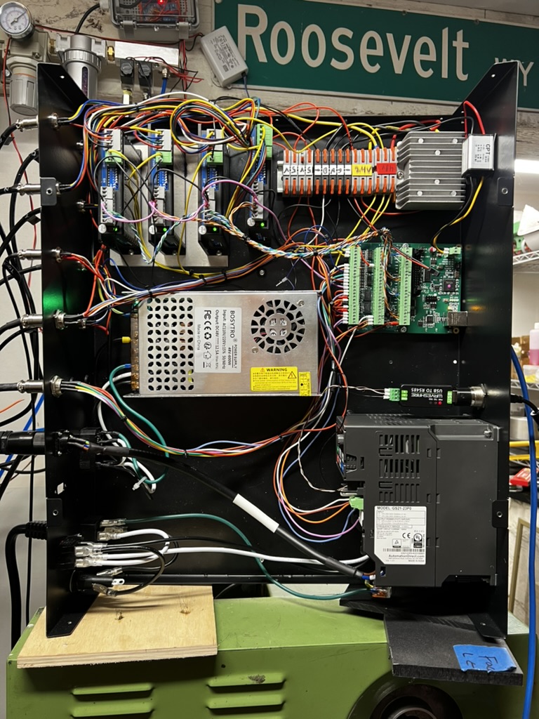
Here is a picture of the box for those interested.
Forgive some of the messiness and the misaligned contactor. Wiring a control box is new to me. I am waiting on more wire to clean up some of the ugliness and mismatched wire colors.
Here are the issues that needed to be tackled:
The VFD is not configured to allow reverse. It needed to be reconfigured. The gain on the analog voltage needed to be adjusted as well. There are 2 or 3 parameters that need to be changed to accomplish this.
The Acorn uses sink to ground for its inputs. This does not play nice with the tool setter and touch probe. As a work around I installed a 2 port relay that uses the 5v signal from the probe and tool setter. It is connected to the relays as NC and opens when tripped. This allows the touch probe and tool setter to be detected. It also disables the spindle when the probe is connected.
The stock E-Stop on the MR-1 is only a software E-Stop. It does not actually disconnect power. If the controller locks up or has a problem, there is no way to stop the machine. I bought a Schneider Electric E-Stop with two switches. One is NC and powers the magnetic coil for the contactor. The other is NO and tells the controller the E-Stop button has been pressed.
The limit switches are not wired in a way that is optimal for the Acorn. They can be connected to the controller without issue. However, it takes 4 inputs to get them to work as intended. I cut apart the cable and wired X, Y1 and Z in series. Y2 is wired by itself and shares ground with the others. This only requires 2 inputs for homing. The Acorn will home one axis at a time and square the gantry using the standalone Y2.
If there are any questions, please don’t hesitate to ask. I haven’t installed the control box onto the machine yet and have been bench testing. I hope to get everything back up and running this week or next. I can add videos if there is a demand for it.
You can flip the 48V power supply on it’s side to get more room. Thanks for @MrmachineTX for pointing this out to me. The Acorn board looks quite a bit bigger than the Mesa board that I used, so I see why you had some tough space issues.
I also used smaller stepper drivers, which got me more space on that side of the cabinet.
I kept the stock enclosure for a year, but I just started the project of moving to using Clearpath servos and their PSU doesn’t fit into the stock enclosure, so I’m moving to a new one. I’m pretty excited about doing it over from scratch and arranging it how I want it to be. The new one will also have a door, which will be such a huge improvement.
This is a photo of my stock cabinet re-wired for LinuxCNC from about 9 months ago if it’s helpful. You can see how I squeezed in the DIN rail in the upper right.
I followed your GitHub closely! Your content there and on here has been a tremendous help!
The Acorn is quite a bit larger and the relay board adds to that. Your DIN rail location is exactly where I hoped to put mine. I wanted to mount the stepper drivers and relay board to it. The problem I ran into is once on the rail, the steppers hit the enclosure lid without wires in them. I was able to model and print a rail mount that was low profile but the high power Z driver still needed another 5mm to clear.
I also tried mounting the PSU on its side, but with the 5v PSU on top, there wasn’t much space savings. In the end, I really needed a better enclosure, but this is a good start. I imagine my path will be similar to yours as far as the enclosure goes. I really wish I could have laid it out better, but a new cabinet and required parts wasn’t in the budget at the moment.
I was able to get everything connected yesterday and have a few tweaks to make before I can run a part. The drivers are nice and quiet and the machine moves with authority. My plan is to push it hard to see how fast I can rapid. Acorn has an option to adjust acceleration and I might mess with that as well.
I had no issues with 300ipm rapids using a 48v PSU for the steppers. Faster acceleration is also great, but if you make it too fast it’s pretty hard on the machine because there is a lot of inertia in handling high speed starts and stops. I tried to find a compromise speed that lets me probe quickly (useful for tool length measurements and homing) without being so much that it puts undue wear on the machine.
I’m glad that you found my info useful. I love seeing the conversions and seeing how others adapt the machine to their needs.
I set the control box and configured the software. Everything works except the probe and tool setter. So far, I can rapid 150ipm at 36v without issue. Forward and reverse operate as expected. Homing and auto squaring behaves just as it did before. There are still things to tweak and I have no idea how to use the CNC12 software yet.
The probe and setter issue is the same issue @AlexW ran into. Langmuir exposes 5v to the body and any ground on the machine and/or spindle will prevent it from working.
With the Acorn, they want you to join DC and AC ground. Also, the metal enclosure exposes ground through the mounting holes on the Acrorn, the VFD housing, and spindle power wires. There is really no good way to avoid sharing DC and AC ground short of rewiring everything and using a different enclosure.
To compound that problem, the V2 probes use grounding pads under the screws that secure the circuit board to the housing. So isolating the spring no longer works as screwing the top on grounds the shank to the body.
My fix for the probe was to run a 25awg wire from the spring to one of the mounting screws on the board. This doesn’t interfere with the stylus mount and allows it to move freely. I cannot attest to its accuracy yet.
The bad news is isolating the spring and housing does not work for the tool setter. Since the touch plate is metal and the housing is grounded. There is no way to make it work. I am trying to figure out a way to use that as an advantage. Rather than breaking the connection, using the conductivity to trigger the signal.
I have seen those and similar tool setters floating around. The Chinese tool setters make me nervous. The price seems too good to be true. I have been eyeing probes and setters from https://drewtronics.org/
The tool setter allows for height and tool diameter. They seem well made and reasonably priced and looks to be American made. I am holding off for a bit until I get the machine running well.
After messing with the Langmuir tool setter for several hours, I finally have something usable. I connected ground to a relay with white from the setter on the NO side. I then connected the NC side to an Acorn input. When contact is made with the tool, the ground is connected and the relay trips. At the same time, contact is broken with the Acorn indicating it has been tripped. The only downside is this drains the 5v to ground on the setter so the lights only blink for a brief second and not while the setter is pressed.
The Drewtronics tool setter looks really tall for the MR-1. The cheap one that I linked to is also pretty tall, the MR-1 stock one is a nice height.
Glad you got it working. The relay will add some time latency, so you’ll probably want to make the second probe move at a pretty slow rate to minimize error.
I ended up going with the Drewtronics tool setter and touch probe. I thought I had the Langmuir probes working and damaged the Acorn shorting 5v to ground. Luckily, I could fix it with a $0.40 part. The wiring is much simpler and I could eliminate the associated relays.
You mentioned the Drewtronics tool setter looked tall. I compared it to the Langmuir tool setter on the riser, which I needed, and it is about 1/4" lower. That is, if I can find a way to mount it without making a mounting plate.
I got the $35 one mentioned above and set it up today. I’m getting good enough repeatability for my needs, about .0001 inches using a script that repeated measuring the same tool a couple hundred times.
The Drewtronics looks nice too, but I accidentally smoked my Langmuir tool setter and needed a quickly obtainable replacement.
Internally it is just a simple pair of switches — it has no electronics. I haven’t setup the air blast, but that’ll be a nice feature too.
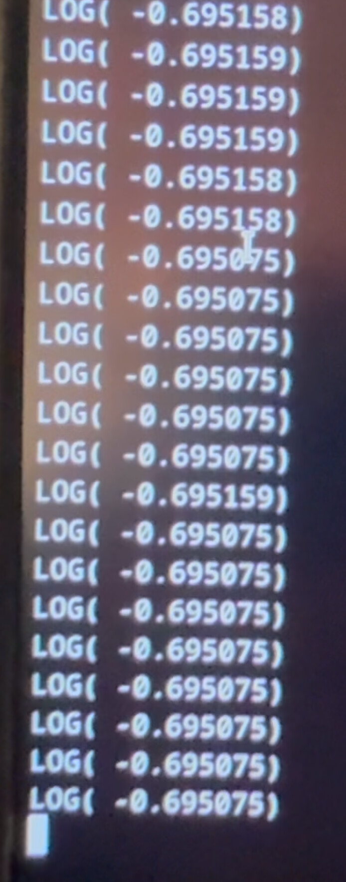
Here is a screenshot of output from repeated testing:
Two complaints are that I did see more variation in results on the first 50 or so measurements with a total variance of about 1-2 thou. It dropped about .000075 (probably 1 step) every 3-4 samples until it settled out and bothered between two values. I expect that this was due to springs settling from initial use, but I’ll need to see if it happens again after the machine rests.
Since you are also replacing your probe think about putting a probe sense wire into your system. I did this last night using a 4th pin on the connector (so VCC, Signal, Ground, Probe Sense) that just sends VCC back (through a 10k resistor) to the a 2nd input on the controller when the probe is plugged in. This makes that signal go high as long as the probe is plugged in, and low when it is unplugged.
LinuxCNC (hopefully Acorn too) has config option to avoid turning on the spindle if a specific input is on. I also plan to change my tool change code to check for the probe to be plugged in if tool 99 (probe on my system) was selected, so that a probing operation isn’t started when it is unplugged.
I am glad that lower cost tool setter is working for you. I will have to keep it in mind. I have been burned a few times with “too good to be true” prices and have adopted the by once, cry once mentality.
I setup the Drewtronics devices late last week and they are working well. The tool setter cable was longer, but still too short to reach the control box. I did wire in a probe sense circuit for each of them. Acorn has an option for probe protection so it will lower jog speeds and disable the spindle if the touch probe is connected. On the Acorn wiring is a little different since it sinks to ground and does not detect a high/low signal.
I used a 4-pin GX12 connector and bridged pins 3 and 4 on the female side. The detection loop is closed and input(s) activated when the probe is plugged in. I purchased the CHIPS add-on for Acorn which requires a detection circuit for the tool setter and touch probing routines.
My one criticism of the Acorn is the lack of inputs. There are only 8 and adding more is substantially more expensive. The tool setter and probe take up half when using detection circuits.
Oh, 8 is very limiting! The Mesa 7i96S (the board that I used for LinuxCNC) has 11 which got me started but became an issue, so I recently added an $80 I/O board called the Mesa 7i84 to get another 32 inputs and 16 outputs.
I feel a lot better with this, now I have some things that I wanted but couldn’t afford I/O for like individual fault signals from all 6 motors (5 axis, 1 spindle).
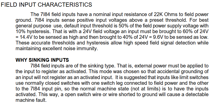
The 7i84 also sinks to ground. The 7i96S is very flexible in how you configure the inputs. This is from the 7i84 manual:
Nice dude, I did the acorn switch on mine too, and clearpath servos, just 1 stepper on Z instead of brake, but Love those motors, and love the board, I’ll post some photos shortly…
I’m confused. you mentioned the stock VFD. Isn’t the stock spindle an AC servo with a servo drive? I have and acorn board but this is the part I’m confused about. I’ve already upgraded all my stepper motors and have an 80v PSU wired up. I’m just unsure how to hook the factory spindle into the acorn board. would happen to have more pictures / description of this process. Thank you so much for the info you’ve already posted it’s extremely helpful.
It is still a work in progress, but it shows how the servo drive is connected to the Acorn. I also use the driver encoder to get actual spindle speed. I am hoping to implement tapping at some point. There are some quirks on getting the driver to operate in both directions using the board outputs. I have that wiring drawn out on paper, but not in the computer yet.
Also, you will not be able to use the stock tool setter and probe. The Acorn board really wants everything grounded to the frame. With 5v being exposed on them, you will cook the electronics in each sooner or later. Drewtronics probes have been working very well for me. They are cheaper than Centroid’s options but more expensive than the Chinese stuff you can get.
Give it another shot. I forgot I didn’t make it public. It should work now.
I read through your original question and if you see VFD in this post, replace it with Servo Driver. I was in the weeds when I originally wrote everything and had the terminology mixed up. I tried to edit the previous posts, but it looks like it locks them after some time