I used white also, and am very happy with it! Looks good!
1 Like
You are a true craftsman. What beautiful work! Anxious to see how the auger works out. That looks like a great idea.
Thanks! That means a lot to me.
I’m excited to get this machine up and running!
It’s definitely time for an update! Ignore the temporary 220 power, my electrician has been slacking on running the permanent power to the spindle.
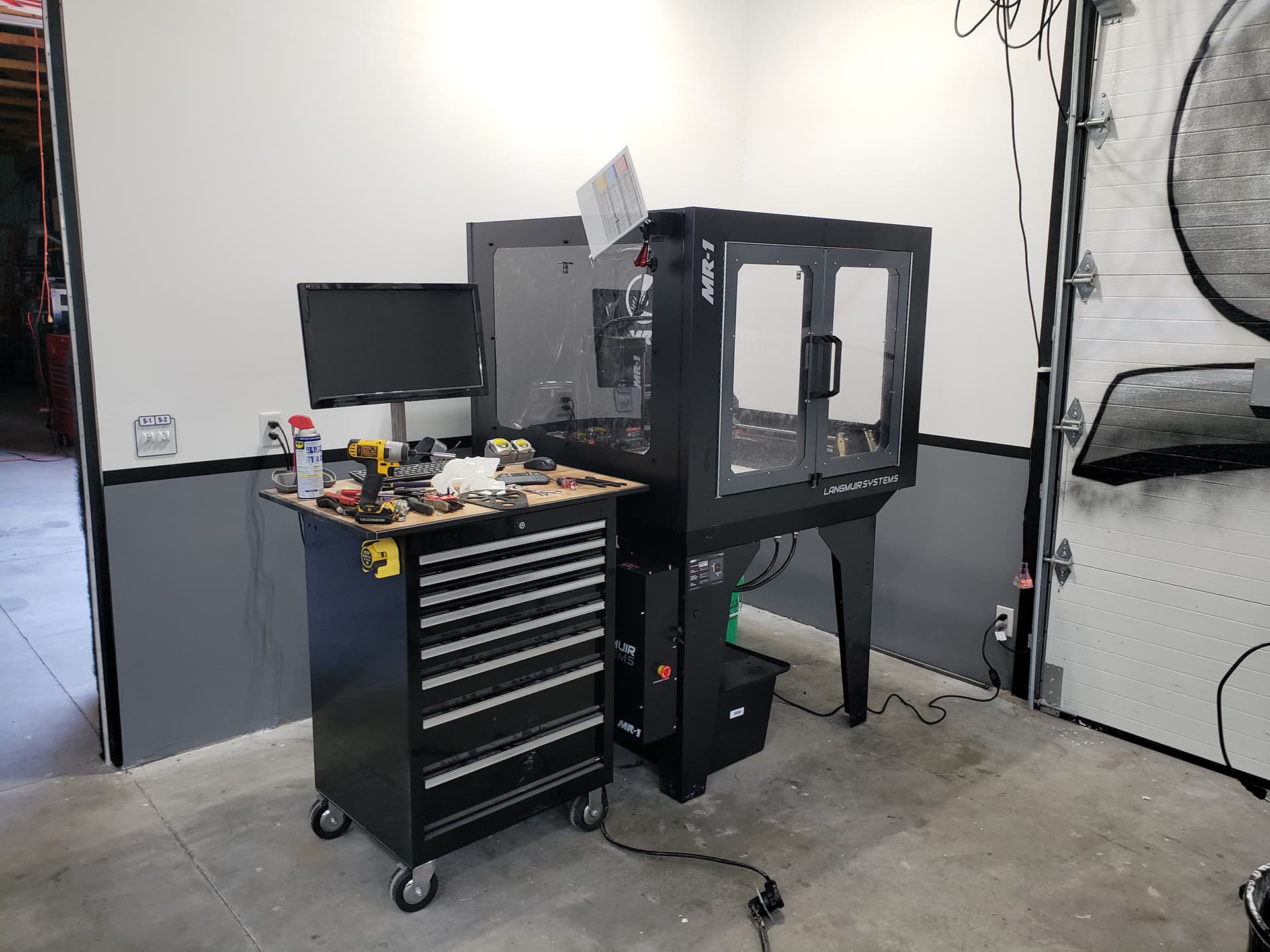
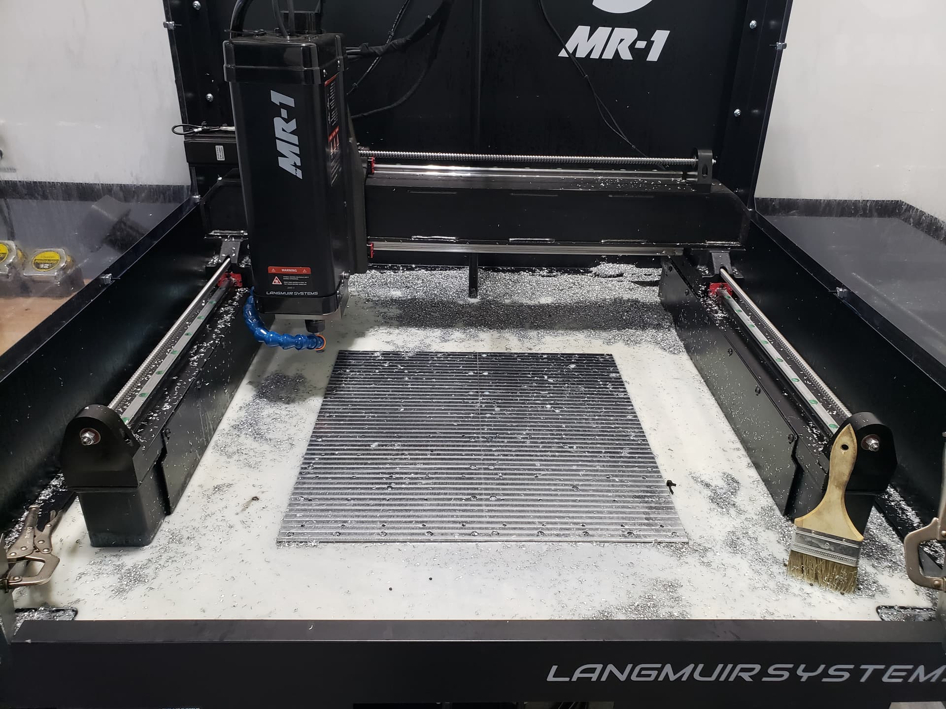
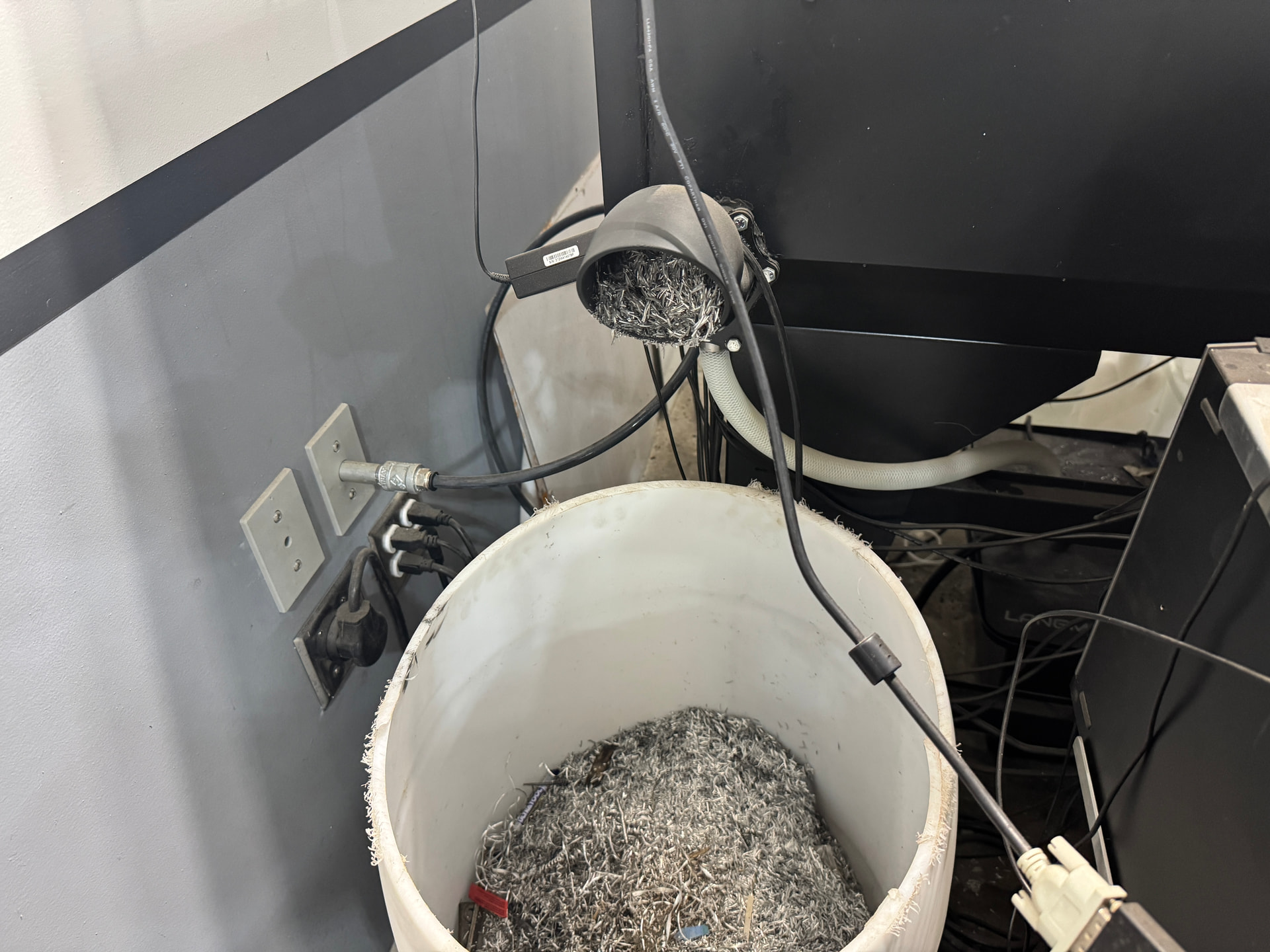
The assembly is basically complete and the top surfaced. I used a 5/8" 2 flute insert end mill to surface the table and it did a nice job (accusize industrial w/ apkt inserts).
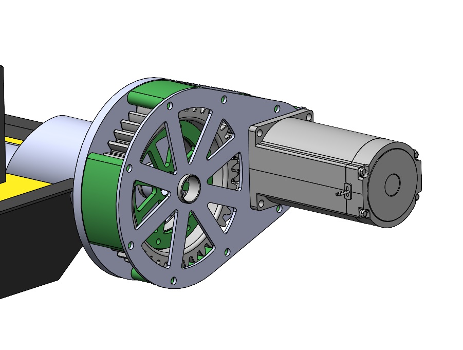
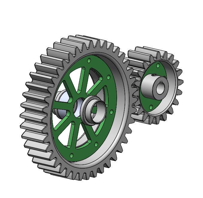
I’m working through mods on the enclusure and my chip auger system. I have the design completed for a gear reduction system and a cheap reversible gear motor. I 3d printed all the gears and the rest of the parts were laser cut out. All components are in house now so I should have an update on the auger system soon.
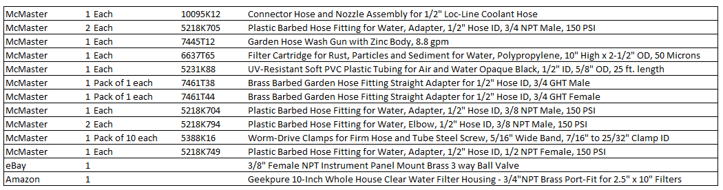
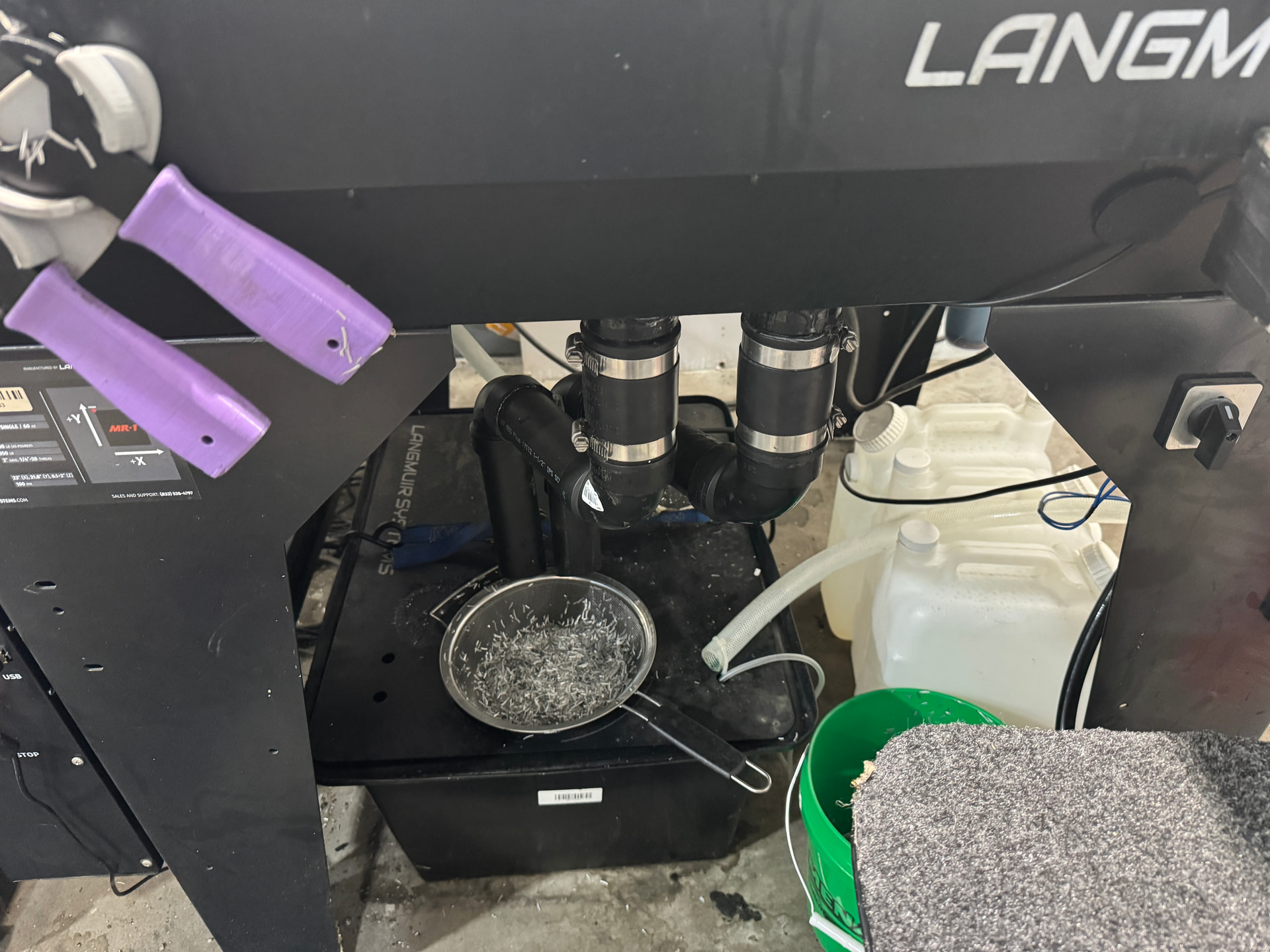
The coolant system changes include adding a filter, 3-way valve, nozzle, and upgrading the entire line to 1/2". Initial testing without the filter and auger shows this might have been a mistake as it filled up faster than it drained, basically becoming a bathtub. The filter will knock down the flow rate some and with the auger I’m hopeful the drainage situation will improve. I can always throttle the flow rate if needed.
Langmuir coolant mods.txt (1.5 KB)
I’m embarrassed at how long this has taken but it happens. Some cool stuff hopefully coming soon.
3 Likes
Looking wonderful Carter…
1 Like
Hi Carter, do you happen to have any updates with how the auger is performing?
I should make a video on it. I definitely learned a few things…
In short, it works and moves chips into a 55 gallon drum. I wish I had sunk it a bit deeper down into the table, as it pushes a lot of material to each side of the outlet pipe. The motor, gear reduction, etc. are all good.
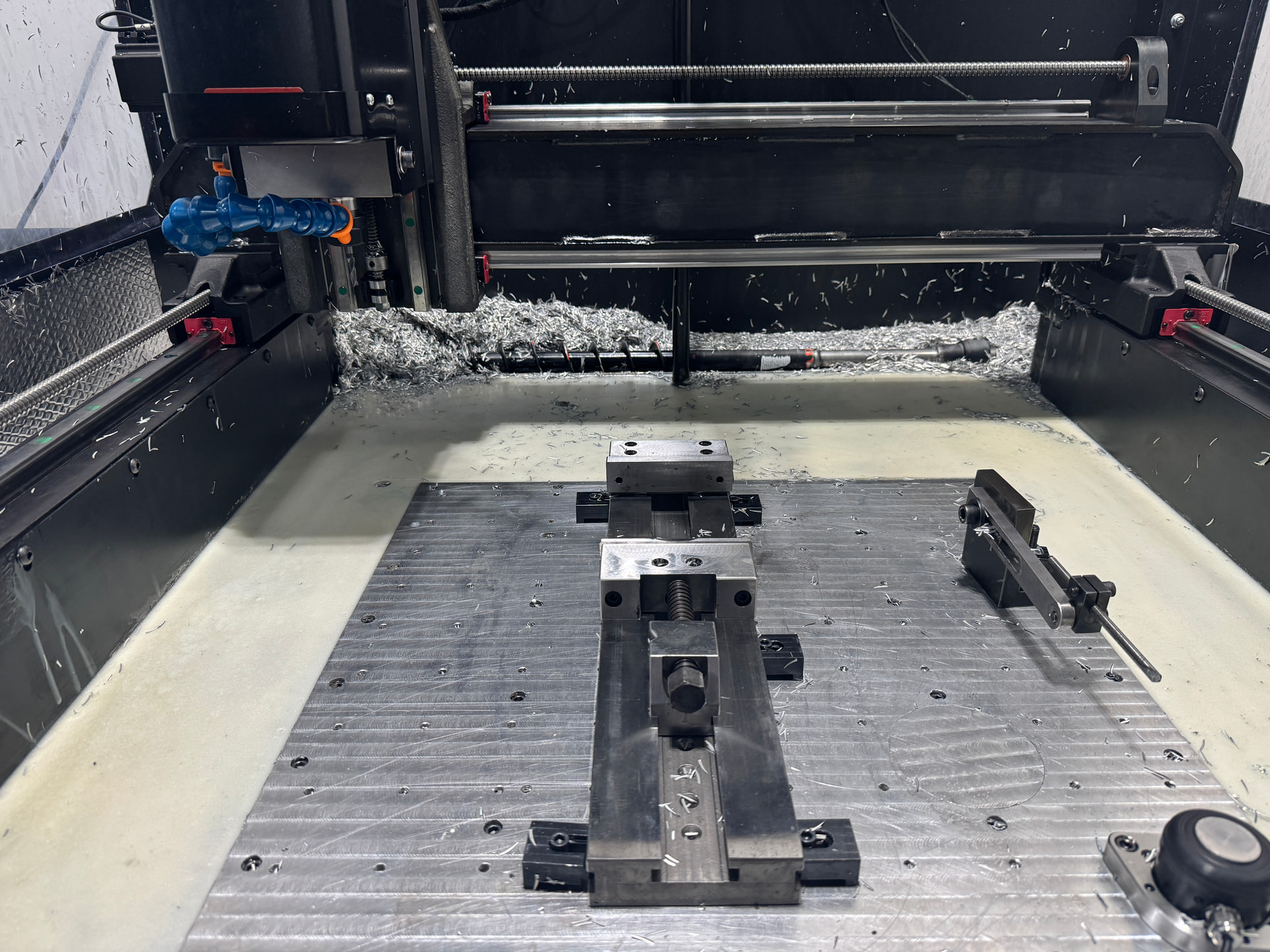
I tried to put drain holes below the auger that feed back to the coolant tank. The problem is they clog quickly and there isn’t a good way to get to them.
2 Likes
Actually I forgot that I have a video on this…

2 Likes
Thanks for posting an update! I was curious how much chip would end up getting pushed back out of the auger tube sides. From what I remember of the Haas vf2 auger setup, the screw was 75% of the way under if not 100% under where chips would fall. Its hard to see in your video but have you added a garden hose nozzle to your coolant pump? Wondering if that could help you for cleanout instead of needing to take off the side panels and use the shop vac.
Yes, I upsized all the lines from the coolant pump, added a filter and a 3-way valve so I can switch between the nozzle and a garden hose nozzle. The valve also lets me throttle down the coolant flow.
I do run the auger and “push” chips with coolant. It works ok-ish. Aside from replacing the limit switches I don’t pull the side panels.
Reposting same pictures from other thread just because they may help somebody:
1 Like
Zip file attached with a step file of my auger system. As Khorshid has noted, the screw might be better if it were lowered relative to the bed. If I were to do it again clean slate, I might bob the rear of the machine flat and then bolt the auger system on as a complete accessory.
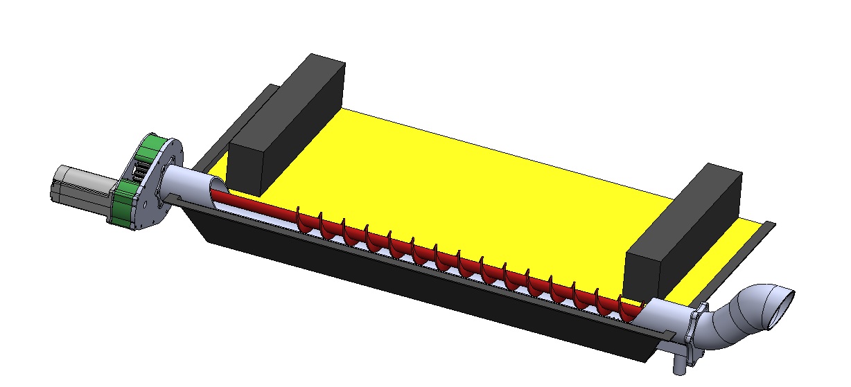
Langmuir MR1 Chip Auger System.zip (4.5 MB)
1 Like