Is there a file (or has anyone created a file) that has the coordinates of the 1/4-20 thread locations so I can create jigs and clamps? I know the holes will be offset according to the home AND if the plate is not square to the machine during assembly - but wouldn’t the file still be helpfull if I found the exact coordinates of the closest hole and the furthest hole? Could a person do the math (or AI do the math) to build that file? If this file does not exist or it is not worthy, what do you propose is the best way to find the locations? I do not need ALL of them of course, but six or so would be nice.
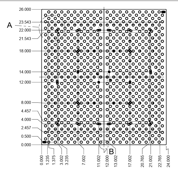
Pretty sure SMW’s print has those dimensions you can extract from their blueprints for their baseplates.
2 Likes
What is SWM, sorry, I am new and the machine is 2nd hand.

What you posted there is not the plate in my machine I do not think…I don;t have near that many holes in my plate. Is there any drawings of the plate that comes with the MR1?
maybe you are saying the holes can be extracted from the drawing… I will research some more.
The Sauders plate is an exact copy or slightly larger ; only the tolerance is far superior. To my knowledge, the drawing above has the same hole pattern.
I’m not really sure what you’re doing. As long as it’s flat, you can bolt down anything you want. Maybe you’re overthinking this? Or maybe you have a plan.
Your locations will be totally unique to your machine. With variance between the two plates, to where exactly you placed them in the concrete, it could potentially be significantly different from machine to machine.
I made my own fixture plate with reamed pin holes and threaded holes, squared and located within the machine, bolted to the baseplate holes. It works really well, with repeatability of about 0.0015. It’s really the only way you’re going to get any accuracy and repeatability for fixturing.
Or you can mortgage your house and buy the same thing from SMW. lol
1 Like
I looked it over last night and I guess you are right. There is a lot of holes, I just didn’t really notice them all. As for my PLAN, I am building jigs that will bolt down to the base plate. Those jigs are custom to the article I am machining. Instead of modify the base to hold my items each time, I can just install the jig plate for each item. The jigged items will run 4-8 items before I switch to a new jig. The idea of course is that my jigs are highly universal so they can mount multiple things before I have to swap to something else. I could simply modify the base plate possibly, but that sounds like a no-no as I can not “replace” it if I drill the shit out of it.
1 Like
This is my plan. Again, I just thought maybe I could short cut the mounting locations if I had a drawing that called out the 1/4-20 hole locations in the base plate. It appears the drawing above might help.
When you created your plate did you manually find the bolt down locations? Did you use the prove or just eyeball?
1 Like
I just measured between the holes, and to the edge of the base plate, and between the adjacent holes along the center split. The mounting holes in my fixture plate are oversized to allow me to adjust position and square it up, knowing the langmuir baseplate isn’t that accurate.
Isn’t it just a 2x2" grid?
use the Sanders download and if you can, just buy the Sanders Plates too. It will save you a big headache later and more bolt hole locations plus it’s wider so you can max out your cutting bed more…
1 Like
You can just get a threaded dowel pin and probe all the locations if you want.
Threaded dowel pin locations are only as accurate as the holes were drilled, or the plate was installed and threaded holes must be precisely perpendicular to the table, IMO
Exactly. If you want to make a plate that can bolt to your existing plate then you need to know where the holes are not where they should have been… Your 1/4-20 holes in the new plate will be counter board clearance holes. You can then bore two dowel holes into the existing base plate. Add those two dowel locations to the design of the new plate you’re having made or making. The dowels will make sure every time you take it off and put it back on it’s in the same location.
The current 1/4-20 holes are for holding down not for locating. It doesn’t matter that much were they are. You just need to be with .015" of the location for them to be useable on your new plate.
2 Likes