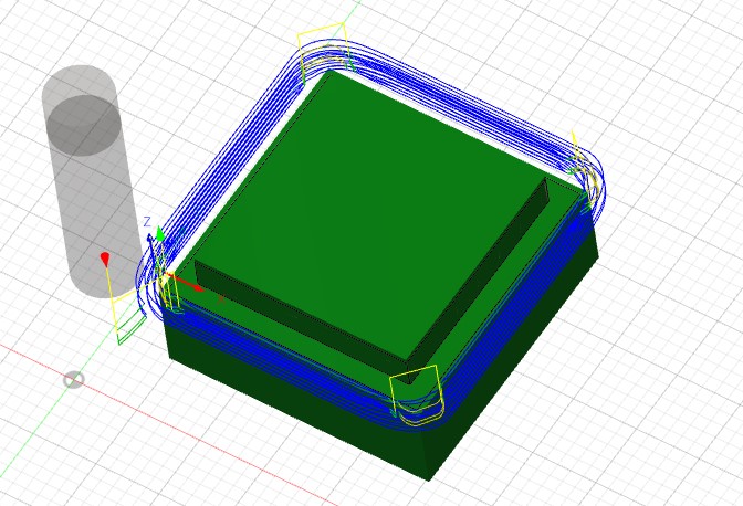
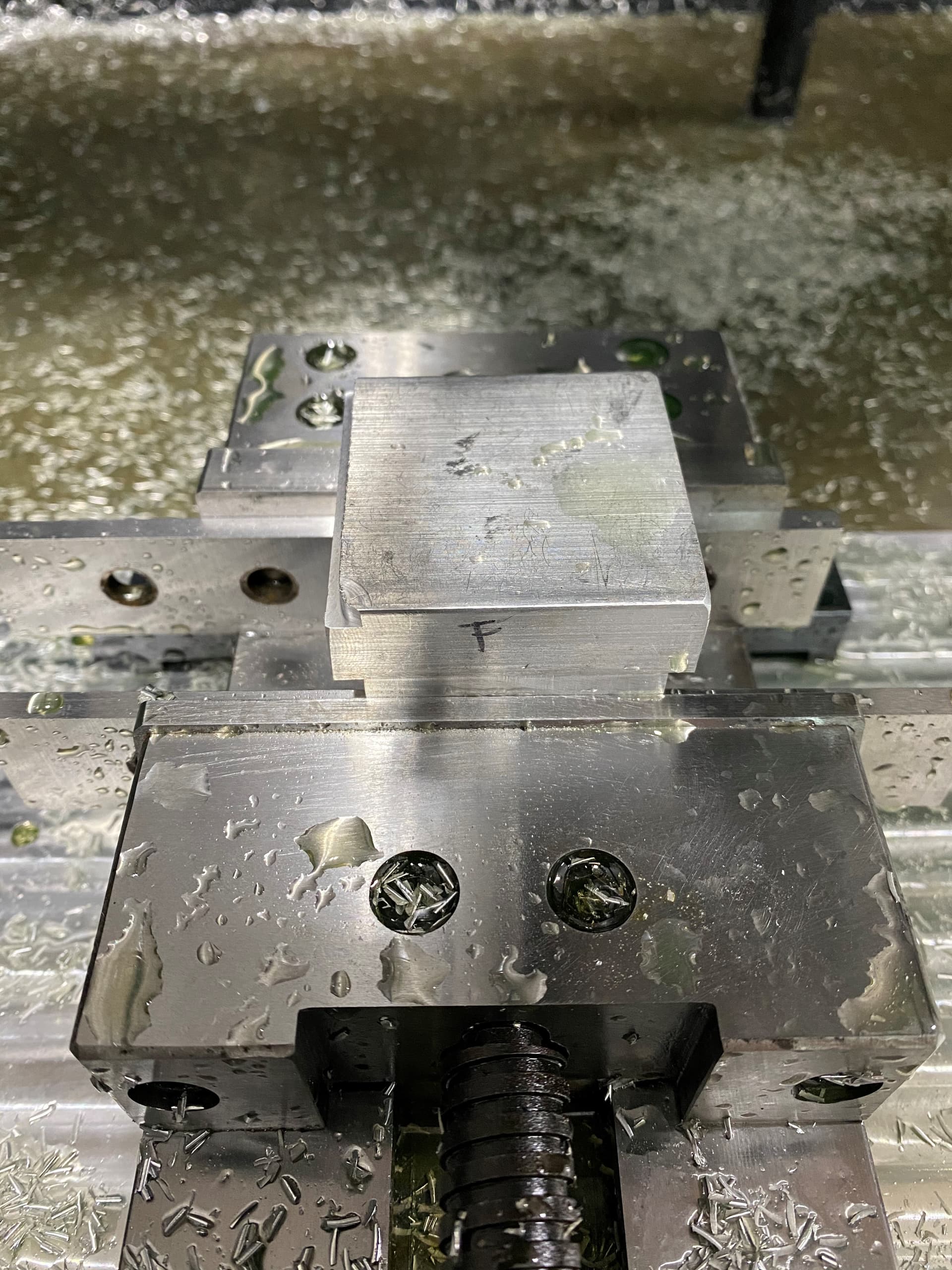
Hey everyone, I finally have my MR-1 ready for some cuts but I’m having some issues. It seems to be taking twice the amount of width of cut and skipping the stock on the opposite side. I’m just doing a simple contour, .025" stepover each pass, and as you can see its taken material on the left side, skipped the back, skipped the right side so I stopped the program. I measured the left side and sure enough it has taken .050" of material. This is actually the second contour piece I am trying, the first one was similar however it doubled the width of cut on the front and skipped the back. The sides came out perfect as they should’ve.
I was thinking maybe something to with travel compensation? Although I did set that as specified with a dial indicator. I am also using the touch probe and tool setter combo. X Y and Z look perfectly zeroed before program is started.
Thanks for the reply. My origin of 0 is front left. I’ve triple check stock sizes and that’s A ok. What I tried tonight was eliminating the touch probe. Same stock, same program but set my 0 with the cutter itself. This time it completed missed the left side of the part and dove into the back side of the stock and took .230" stepover when the total contour should have only been .150". Not sure what else to try. It almost seems to be a random problem, its not like its taking only more material on the same axis every time. I can’t seem to get it to make a mistake repeatedly. It’s also not a small mistake, .003-.005" could be just machine setup, but .080", somethings got to be wrong. Very odd. Any other suggestions?
I suggest to simply issue a movement command and then measure the movement as well as checking the DRO. Maybe there is an issue in the travel compensation. Set up a 3 “ travel in the X direction and see what you get. Do it for all the axis just in case.
Does the toolpath look correct in cut control before you run it? There’s a nice feature in CC where you can hover your mouse over any of the toolpath lines in the CC preview window and it will show you the coordinates at that location. It’s a nice sanity check when you have your toolpaths traveling within thousandths of your vice, holddowns, etc.
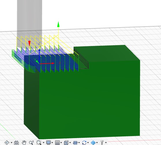
Thanks for all the replies. I didn’t have any problems when resurfacing the baseplate. So I checked the machine compensation with dial indicator, my X was off my a couple thou. The others were fine. I did a manual spindle on command move, and measure DRO distance and actual distance and everything came out perfect. Decided to start fresh with a new piece of stock and program. I used a 1.965" long (x) by 1.5" wide (y) by 1.5" thick. I programmed a step .100" downward and .965" in length. The X and Y dimensions have came out perfect! So that problem must be solved. It must have been something I was doing wrong with the contour program and just haven’t come across what.
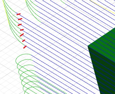
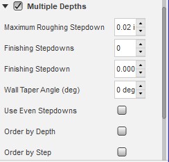
However, the Z took an extra .040" which made the step a total of .140". Now I am just doing light duty cuts here, for now. So I was taking .020" depth of cut. But I noticed afterwards in Fusion 360 I could see the simulation taking 7 cuts downward (which I highlighted red markings in the picture.) With a .20" depth of cut at .100" total, that should have been only 5 cuts. And 7 cuts at .20" would tally .140". So at least this isn’t a random number, everything “adds up.” But I am wondering as to why it would do this. I have finishing passes off.
Consider that when you select the multiple depths and a maximum roughing cut of 0.02” it means that the software will select a certain number of cuts that can be at different depth where the maximum does not have to exceed 0.02. In your case few passes were below 0.02”, and the sum of all 7 passes should have totaled the total depth you established in your design.
Glad to hear your original issue was just fluke. As for your new piece, It looks like your stock extends a little in each direction, and specifically is higher in the Z direction. Could your stock be .040" larger and it’s taking the additional 2 passes in order to get down to where your .100" step begins?
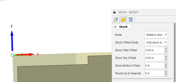
You might want to check your heights tab to see if it is set to stock top or model top. Also check your set-up and make sure Fusion didn’t add anything to your stock dimensions.
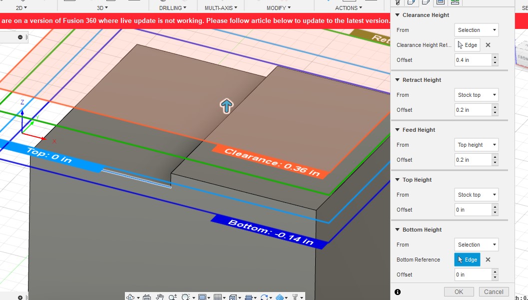
Ahh ok, I went into stock setup and sure enough I have .040" offset. I then confirmed this would take a depth of cut totaling .140" when I went into the heights tab and clicked set bottom to selection, as you can see it displays .140" as bottom.
Thanks for all the replies and assistance! Much appreciated!