Those of you who know, know that the pins on this thing are a PITA—tiny and clustered together. I asked Primeweld Customer Service if they minded (warranty wise) that I change out the connector to something easier to solder or possibly even crimp. Dustin at Primeweld has asked me what style of connector people would like to see on the Cut60 to make the job easier. I just don’t have the background to know what is out there that would be easier for people to execute. Any ideas?
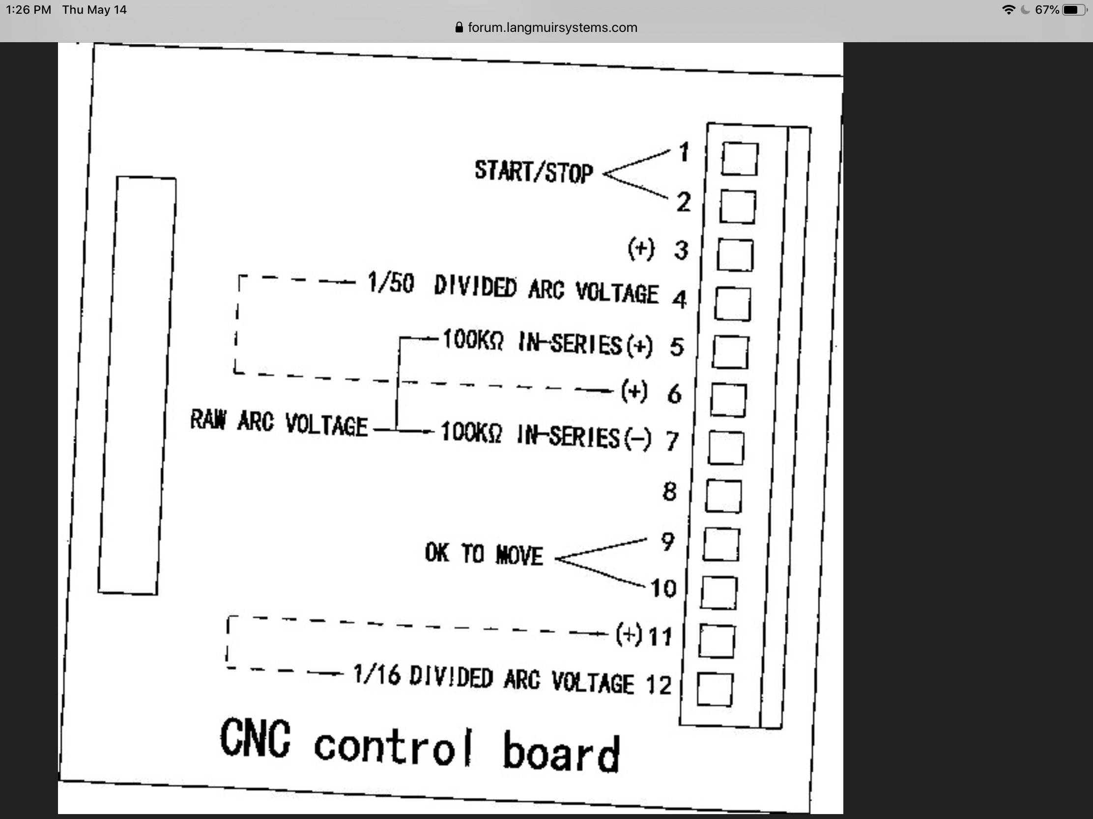
The connector has 12 pins and all but pin 8 are possible pinouts for an assortment of CNC connections, more than the few pins Langmuir tables use.
Soldering is a skill. I used alligator clip holders and a magnifier to solder the pins for my needs. The existing plug works but I can understand people wanting something that is easier with less or no soldering.
The advantages of the currently used plug connector is being small, locks, water resistant. Not sure of other options that could permit those benefits and give “easy” connecting without adding extra cost to the unit.
PW asked, so I’m just trying to help them come up with a more customer friendly solution. I applaud them for caring enough to spec a better connector, if one exists. I just need some help putting them on the right track to a solution. It will be up to them to decide if the cost is justified.
PS I’m switching mine to the 4 pins at 3mm version of the same IP67 connector and capping off the unused wires inside the machine.
That’s a good idea. I think everyone should wire in what ever plug they want to use and get raid of that PITA plug they use.
Or maybe Primeweld should send a plug already wired for every CNC table out their.
2 Likes
IMHO Soldering is a skill and an art, very much worth learning and developing. There are many different connectors in the electronics industry, some way more intricate than what’s on the CUT60. A little time devoted to developing good soldering technique, mitigates the challenges on this and future projects. Just my $0.02
2 Likes
Soldering is a much better connection than crimping, both mechanically and electrically.
1 Like
Nany good videos out there, but here’s a decent, to the point instruction to get one started:
1 Like
@MrHaNkBoT If you do a Google search, you will see that both systems have their advocates, From a practical standpoint, if solder were clearly superior, you would expect to find heavy or exclusive use of solder termination in automotive, agricultural, aviation and marine use. Both are employed, but presently crimped termination dominates those industries. In fact, every electrical system in the Toyotas, Boston Whalers and Kubotas I’ve owned over the past 40 years has employed crimped terminations. I’ve never seen one fail due to either corrosion or vibration. That represents hundreds of years of combined service in a hot coastal climate that sees more than 100 days per year of 100% condensing humidity. On the other hand, I’ve seen plenty of printed circuit boards (soldered) fail under the very same conditions and have seen a few solder joints fail due to fatigue.
Without using Google-fu my guess is that crimped connections are cheaper where they are used, or because it allows for easier repairs. I’ve toured a Molex facility, those connectors are made FAST.
I’ll do some more looking when I’m not on a plane to expand my understanding.
1 Like
@Cletus I don’t have a problem soldering. I was just asked by the company to help them find a better connector, solder OR crimp. Either way, I have also suggested that they rearrange the pin out to separate the on-off pins from the divided and raw voltage outputs. It unlikely that anyone will use more than one set of voltage outs, so that will also remedy one of the problems. For my shop use, the 1mm solder buckets didn’t cut it, so I’m going to 4x3mm. It will make a much more robust connector, especially given the weak strain relief.
It’s not that simple. Long-term corrosion resistance, fatigue resistance, field repairability and strain relief also play into it. And other stuff. I trust crimped connections more just because I’ve seen them hold up so well, but I’m not saying they are better.
There is a big difference between a factory automotive wire cramp and the hobby guy with a dollar store crimping tool.
1 Like
If there was anything personally I’d like to see change about the CNC connector, it would be that it had the pins removed that aren’t connected on the receptacle on the inside of the case. No point in having pins in the way that can’t be used without opening the machine and voiding your warranty anyway.
But I already have my machine, so it’s not really about what I want, just what I’d change from my experience. My much bigger issue is the color scheme on the wiring harnesses that come with the CF Pro. I’ve complained in another thread about black being the positive wire. Just pure craziness.
And no, I don’t subscribe the the “electricians use black for hot” excuse. This isn’t an outlet in the garage, it’s electronics.
That would be a good idea. The plug pins were not installed in the plug. You could solder the wires to them as needed and push them it the plug were you need them.
You think a hobby guy with a $4.99 Chicago Electric soldering iron is going to do as good a job as a person who sits at a solder station 2000+ hours a year?
1 Like
@mechanic416 Seriously, George, you work with these things… do they really need 50:1, 16:1 and raw + 100ohm resistor outputs?
I think the Cut 60 only has a 50:1 divider. (it has more than that I was wrong)
I’ll defer to George here, but at the very least the voltage divider steps it down to a voltage that is a little less prone to arcing across an air gap, and less likely to shock you or anything else it touches with high voltage should something happen to allow you to accidentally come in contact.
Why of course you do. Unless they only sell the plasma cutters to the people with a Langmuir table like they do with the Razorweld 45.
I talk to people that have all kinds of tables, some they buy some they make from parts and the THC uses different settings.
@MrHaNkBoT This is (or was) the pin out diagram. I’m not making it up!
@mechanic416 Thanks, I just didn’t know how common the voltage outputs are.
Sure enough, I looked for the manual online before I replied but couldn’t find one. Thanks for posting that. I edited my earlier comment so no one is led astray by my original post.
1 Like