So I am trying to cut some small slots into a project that are .075 x .80 and when I do my set up it comes up with a linking constraint. I have tried about everything to shrink down my lead ins but I need them for my other holes. Is there something that I am missing to get these cut?
Change the pierce clearance from .06 to 0 and see if that fixes it.
No it didn’t make any difference at all.
B What tool set up / cutter are you using?
.6 mm .8mm?
Nozzle clearance?
Are you setting in computer compensation & center?
Typically when I cut just lines/slats
All settings are 0
Your tool setup (I have 2 I currently use )
.050” for my .8mm nozzle
.023” for my .6mm nozzle 25A and below
Depending on the slat size your trying to cut
Your current setup/settings can’t accomplish it with the cutter
From tests I’ve run I know I get a 0.031” Kerf width on .105” steel @ 70 ipm - 30A - .074” Torch height & .8mm nozzle
With the cut being perfect and nearly no dross free so I might select my smaller tool for my setup even though I’m using the larger .8mm
It works for me.
With my machine RAZORCUT45.
If you could attach your file or screen shots of your setup it would help
I also create a filled circle in CAD the size of my expected kerf and set up and run it along and over design area to be sure it won’t cause an issue with Clearance’s…
1 Like
That’s a clever idea. Especially with small odd shaped holes & text.
1 Like
Just carried it over from my wood CNC designing work flow but thanks, it has saved me quite a few times from ruining a large intrique piece more than once.
Off course before I started it I did mess up a few😉
1 Like
Very much a newbie here, but trying to read and learn more everyday. My question is you say you designed a filled circle in CAD the size of your expected kerf and run it along over design area. I just don’t quite understand, but would like to try anything that helps me also. How do you do it? Probably sounds like a stupid question to someone who is very good at all the programs and software.
Another question, who has the 6mm tips? I have been looking for them for my Razor weld 45, but am only finding 8mm.
JDean, I do 99% of my design in INKSCAPE, a free open source vector graphics program.
Wether from scratch or importing free Svg or jpeg images from the internet to start with.
When I need precision I’ll use FUSION 360 to start my sketches/designs.
Once you have your design you just draw a circle ![]() filled whatever color you want.
filled whatever color you want.
I then drag that specific size circle which represents my CNC End mill size or my expected Kerf width using the plasma cutter.
I have done cut tests for every thickness of steel I cut for my projects.
For example:
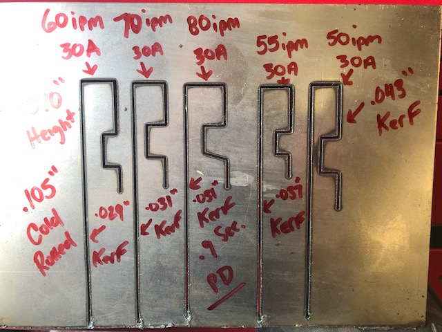
I know what my Kerf width is because I used these results from my test on this sheet @ .105”
So if I’m gonna use 70 ipm at 30A on this sheet thickness I know my average kerf width is .031” of an inch.
So with that I’ll make a 0.031” inch circle in my CAD. And run it along my design in the pockets, corners , curves etc…
If my design paths - (the lines that make up your drawing) are to close you’ll see the cutter path might cut out other areas right next to its path that your not trying to cut.
And if anting won’t cut properly due to the make up of your design.
It’s a quick method to find sketch/design areas that may have issues with the cutting kerf width bring to wide.
Then I can modify the sketch so it will not be an issue… using Nodes tool or whatever btool that’s in your particular software u use.
.6mm nozzles are all over the internet
And and gamblegarage who’s a member here also sells them.
They are for thinner sheet though, like 24-22-18 gauge.
If you use anything more then 25 Amps on your machine don’t use the .6mm nozzles!
They can’t take that Amperage! And will be worn out after 1-3 cuts maybe more or less depending on your cut time on your piece.
AMAZON sells them as well.
With the .6mm you can get a Kerf width down to .019” for fine cut detail on thinner sheet steel or anything else
& WELCOME.![]() to the FORUM.
to the FORUM.
I was CAD clueless less than 2 years ago
But constant tutorial after tutorial I’ve begun to improve quite a bit in understanding how my software works for design.
Just pick a software and dig in and spend the time with the tutorials and practicing.
I couldn’t stand FUSION 360 Last year but this year I really like it and I got past the learning curve frustration.
3 Likes
Awesome. Thank you so much for your response and explanation.