I get the red triangle that says errors but when I open the dialogue box for the errors it’s empty, any way I can find out what the errors are?
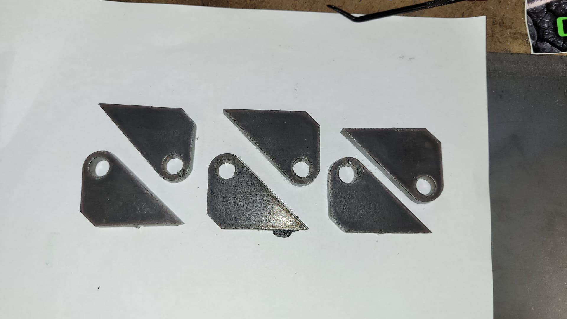
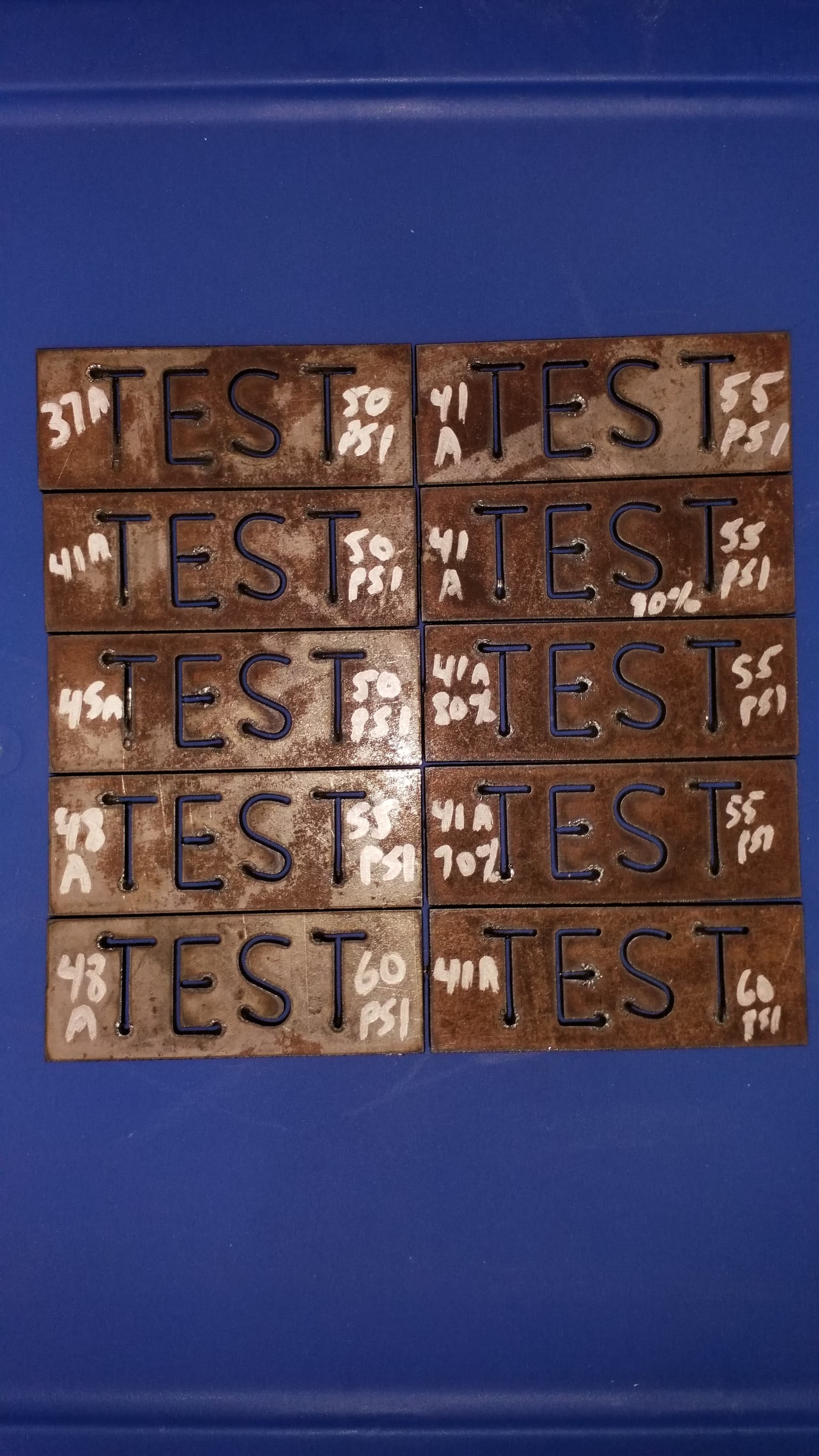
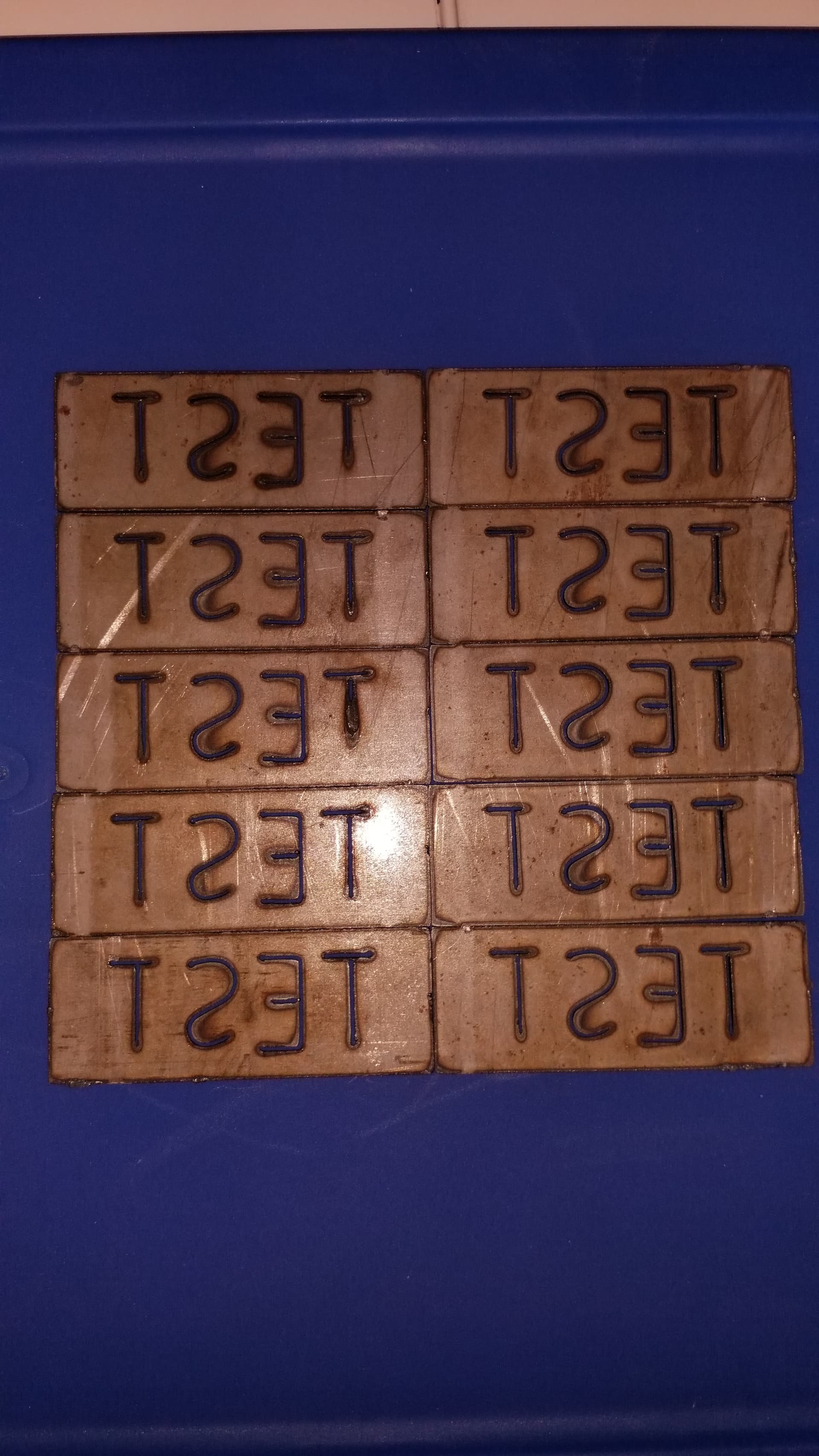
I figured out I think most of it, thanks for the great video Tin. I had an issue at first with the operations tab, I didn’t select the cut pattern for the letters AND the base piece but once I figured that out it was pretty smooth sailing. Since I don’t have my own library of material settings I decided to run off a bunch of these test pieces with different settings to try and dial in the best settings. Here are the results, the first one cut was at 37A, 90 IPM and 50PSI (I thought it was set at 55PSI). The markings on the front of the pieces are Amperage on the left, PSI on the right and where you see % marked that’s the % of 90 IPM I had it set to. Really happy with most of these pieces actually but a few definitely found the edge of the envelope.
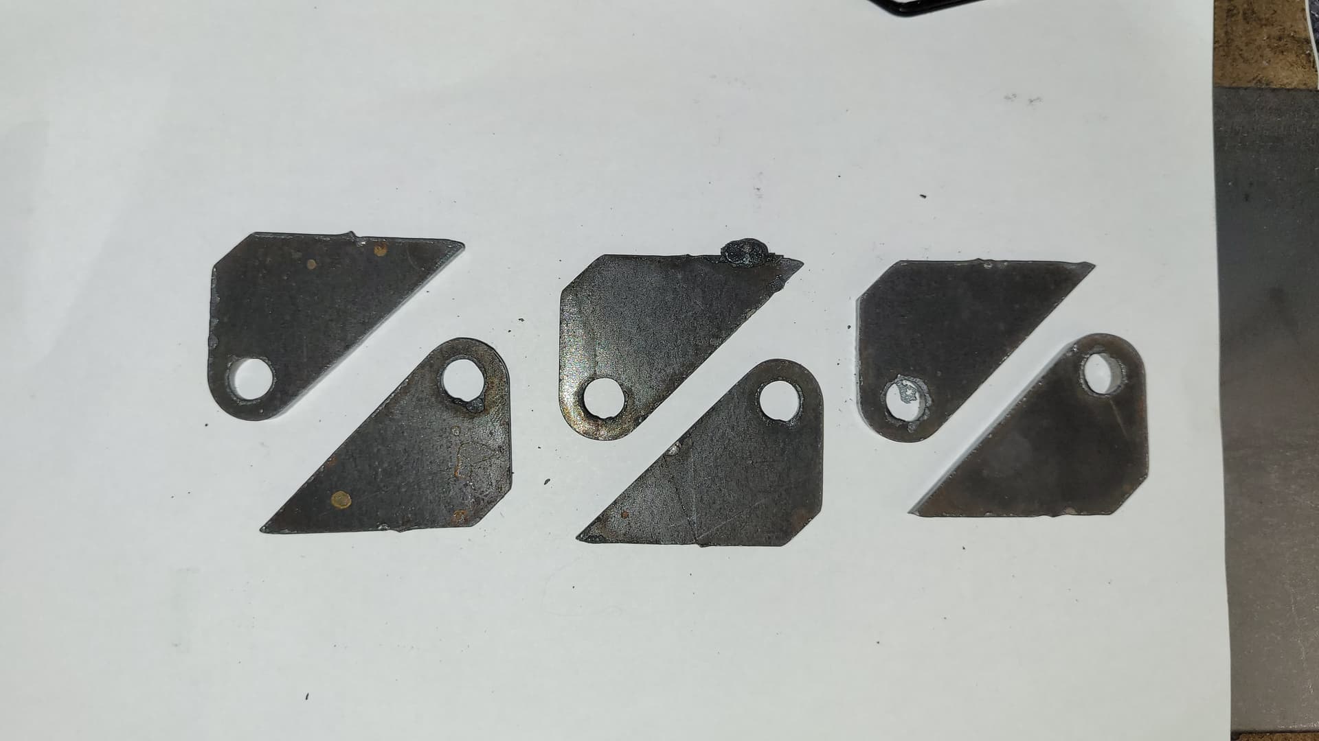
The picture below has all the test pieces in the same arrangement just flipped over so we can compare the dross sides.
P.S.
This is 1/8" stock, the settings chart for the Cut 60 doesn’t have 1/8" listed it goes from 16GA to 10GA to 3/16", it doesn’t list 14GA either and 1/8" and 14GA will probably be the two sizes I use the most so I need to dial in the settings on them.
3 Likes
Nice job. When I read the title of this thread “what should I start studying?”
My first thought was that the real learning starts when you start burning.
It is really wonderful when you start being able to make the products that you want or need. You are off to a great start.
I tried to use Sheet Cam but decided to stick with F360. With input and postings from @toolboy, @TomWS, @jamesdhatch, @Cletus, @ds690, @TinWhisperer and others, I feel comfortable with my setup now. If you get into the real art pieces, Sheet Cam will be your friend.
2 Likes
The fix and unfix button in the sketch environment will take green fixed sketch lines and unlock them making them blue unfixed sketch lines. (Or vice versa)
Black sketch lines are fully constrained. Which means they have one or more constraints applied to them that make them completely immobile.
Since I posted this link they have added the red sketch line which shows a inside contour in a closed profile.
2 Likes
Quick question for you, I designed some gussets and nested 6 of them in Design, went to manufacture and it’s showing me the orange warning triangle that says “One or more passes were discarded due to linking constraints.”. What are linking constraints and how can I identify them or when they may become a problem?
What this means is that a combination of your parameters ( kerf width, Pierce clearance, lead in radius, lead in, lead in angle, and/or lead out) adds up to more than what fusion feels it can fit into that shape so it discards that contour ( small shapes or holes) and does the tool path for the contour ( small shapes or holes) and can not fit those parameters in.
When you take a look through your tool paths you’ll see that it is discarding one or more contours. You may start a second operation and pick these miss contour(s) up with different parameters while leaving the yellow alert icon on the first toolpath. This won’t hurt anything.
The other option would be going back and editing the first tool path reducing those parameters so it may pick up these contours ( small shapes and holes)
2 Likes
I deselected lead out and reran it with no warnings so looks good. I only had lead out selected because it’s 1/4" material and has room to work outside the contours. In the Langmuir video they said don’t use anything on the Height box in the manufacture window unless you have a THC and that they would cover it later but they never did so I always just skip over the height box. I have a THC , where can I find how to make adjustments in the Height tab in the manufacture window?
I have a group of gussets nested up and when I extrude them they all turn brown and the holes disappear, how should I extrude them all without losing the holes? When I try to extrude them one at a time the first one extrudes and the rest disappear.
How did you make this group of gussets?
Did you copy and move sketch geometry?
Did you copy move a body?
Or did you copy move a component?
Did you use the arrange feature to make your nest?
It’s hard to visualize what you have going on.
I made 6 altogether, I copied the first one twice, then copied the group of 3 once. To copy the single I boxed it, right clicked it then checked “copy” in the dialogue window then moved it. When I did the three I dragged a box around all three then right clicked on one and selected copy same as the single one. In the end I wound up just backing out of the process to before the extrusion, then I went to manufacture without extrusion. I actually cut the pieces without extruding them I just made sure to manually set the retract height and travel height so the torch didn’t get hung up, I was cutting 1/4". It actually worked. I was losing the holes in the gusset after I extruded them and went to manufacture.
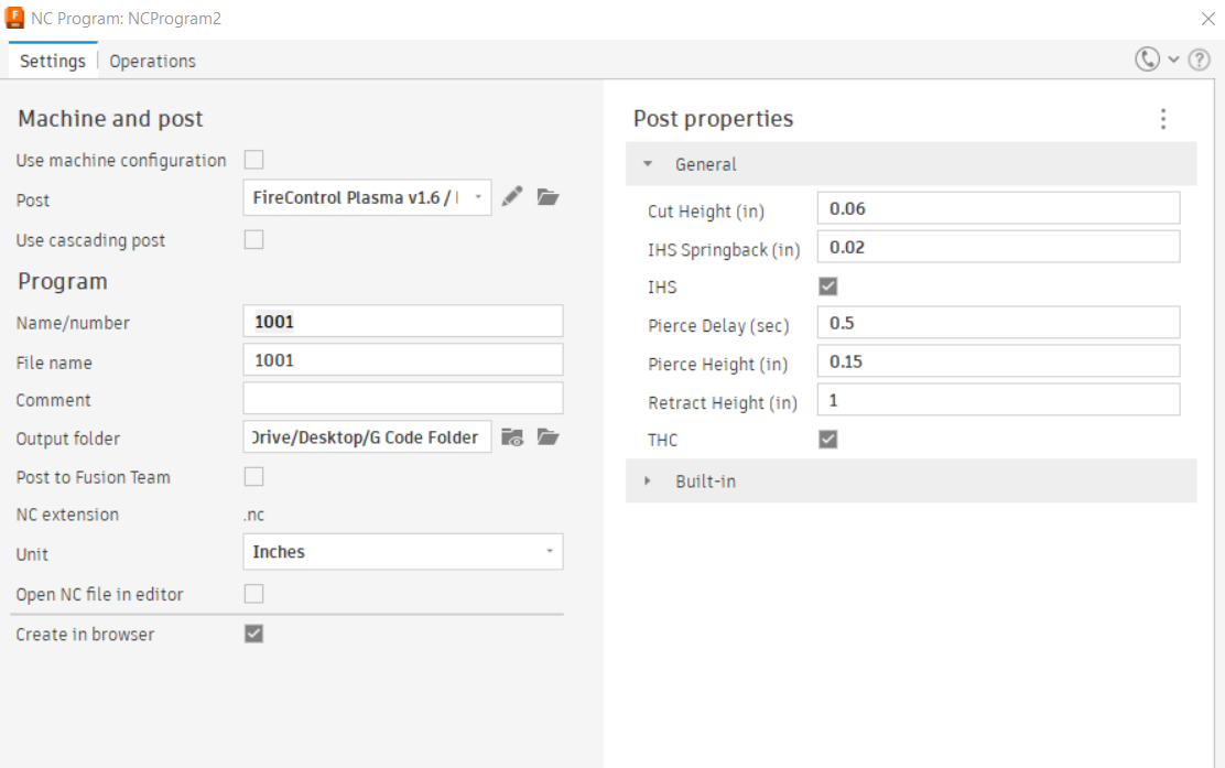
If you set the pierce height and cut height in your CAM setup, the post processor will set the retract height to 1" by default. This keeps the torch clear of any obstructions on the rapids.
Setting the pierce height and cut height is necessary if you have a powered Z axis. Having a THC has nothing to do with the need for those settings. The powered Z axis and the THC are not the same thing.
A simplified explanation is that the IHS system works by lowering the torch until it hits the metal and continues down until it unloads and opens the IHS switch that is attached to the Z axis carriage. It then raises the torch until the switch closes and sets the Z zero at that point. It then adds the backlash and springback amount that you set in Fusion and sets that as the new Z zero. Then it raises the torch to the Pierce Height that you set in Fusion, pierces and lowers to the cut height that you set in Fusion.
All of this is separate from the function of the THC.
2 Likes
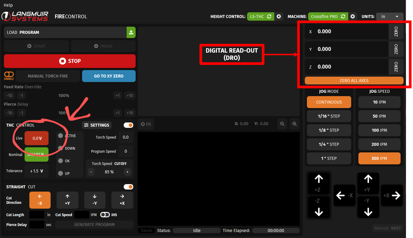
So what do you have to set for THC or is it automatic once you turn in on in FireControl? Also where on the FireControl screen can you see the live voltage so I can verify that THC is working properly?
It would have be interesting to see why your original model failed to extrude properly.
1 Like
I don’t use Fusion, but I believe you have to check a box to use THC in your setup.
You can see the live voltage here
1 Like
Yeah I’m hoping it doesn’t happen again but at least now I know I don’t really need to extrude it.
Got it thanks!
1 Like
You definitely do not have to extrude anything. As long as the sketch geometry is visible it should be selectable in the manufacturing space.
1 Like
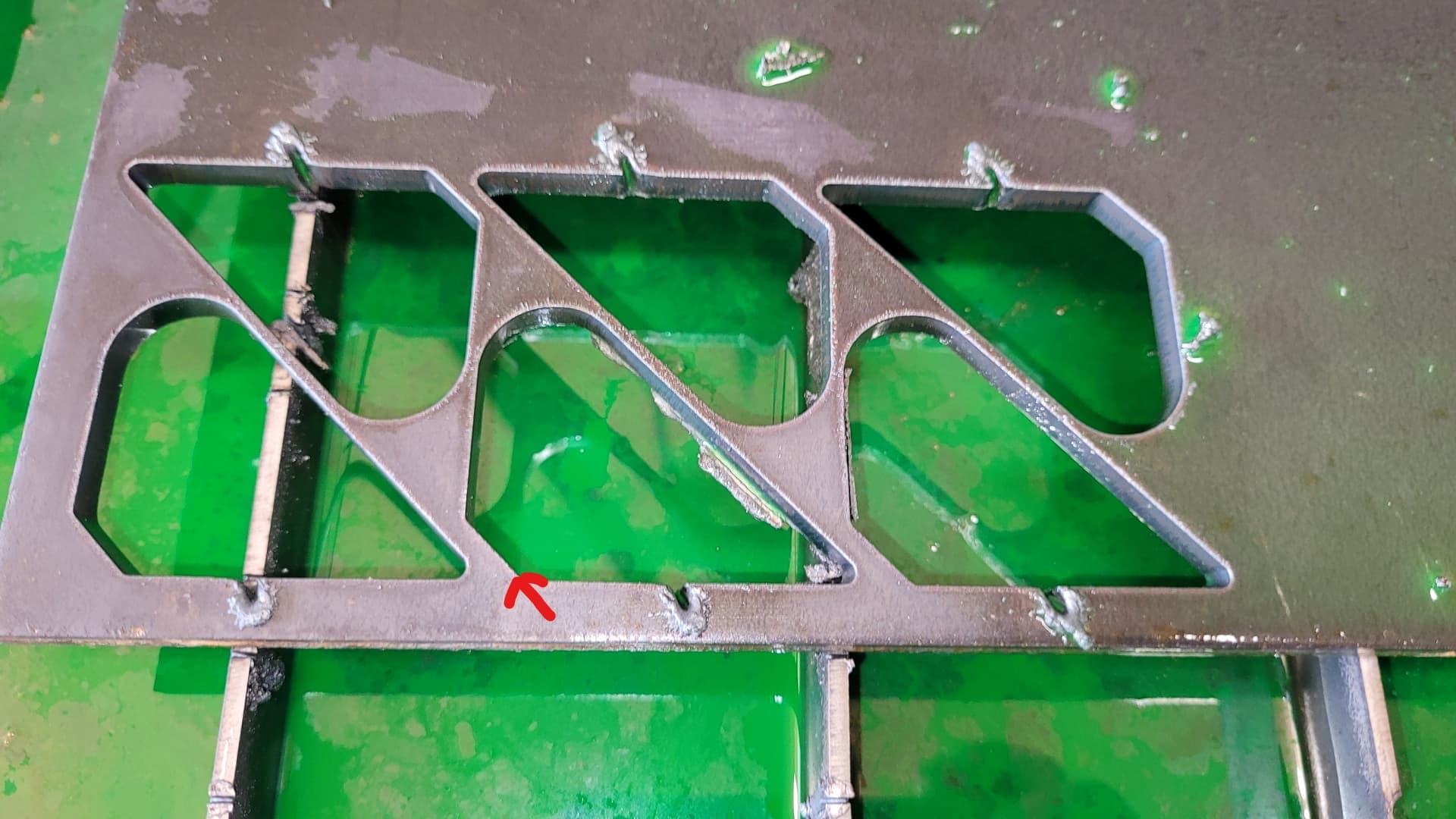
Here are those parts I was trying to figure out the extrusion on. My first run at 1/4" and my first shot at kind of nesting. Except for one big blob of dross and ALL the leadins needing attention I thought they turned out pretty good. Looking at those leadins does anything jump out at you that might be wrong in the settings?