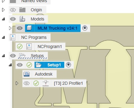
Take a look at this example. When you use the body, it must be visible. In your first example when you were selecting the contours, you could see there was no body visible based on what was showing on the browser on the left side. And sometimes you need to tell Fusion 360 that you are going to use the “face contours”…that is what using the body is doing:
I’m not the most experienced F360 guy, but those points showing up on an Extruded body are something I haven’t seen happen. You might check and see if you have multiple lines on top of lines from inserting the SVG. If so, maybe that has affected your Extrude process.
Just a few other ideas:
During Setup, click the cancel “X” and go to the “Models” drop down and actually select the model (should be saved file name) you want to cut.
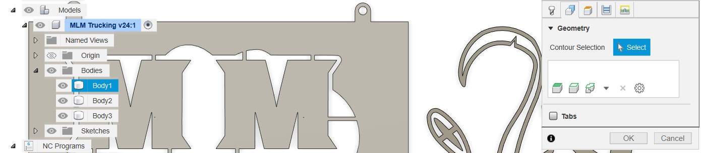
When you select the contours, hover over the Body you want to cut and make sure it turns blue in the list. Here my cursor is on the “M” and Body 1 lights up.
Ok, it’s definitely something with how I originally sketched it or extruded it because following the tips yall have given, I now see that when I try to select the contour, I don’t get the blue border. But if I select one of the sides, I do get the right border. I may just create a brand new sketch and re-extrude and see if that fixes it.
Ok, progress! Recreating the part from the top down view and following yalls advice got me a successful contour selection and simulation. I’m now going to try add my svg logo and see if that works.
You actually solved your own problem. If you look at this GIF that you sent, when you select the side of the body, the selection occurred. When you tried to select the true ‘face’ no selection was occurring. You were actually in the wrong plane in the setup.
You could have made the gcode/manufacturing work out if the “plane” was changed in the SetUp even when you do your design on the “Front” plane.