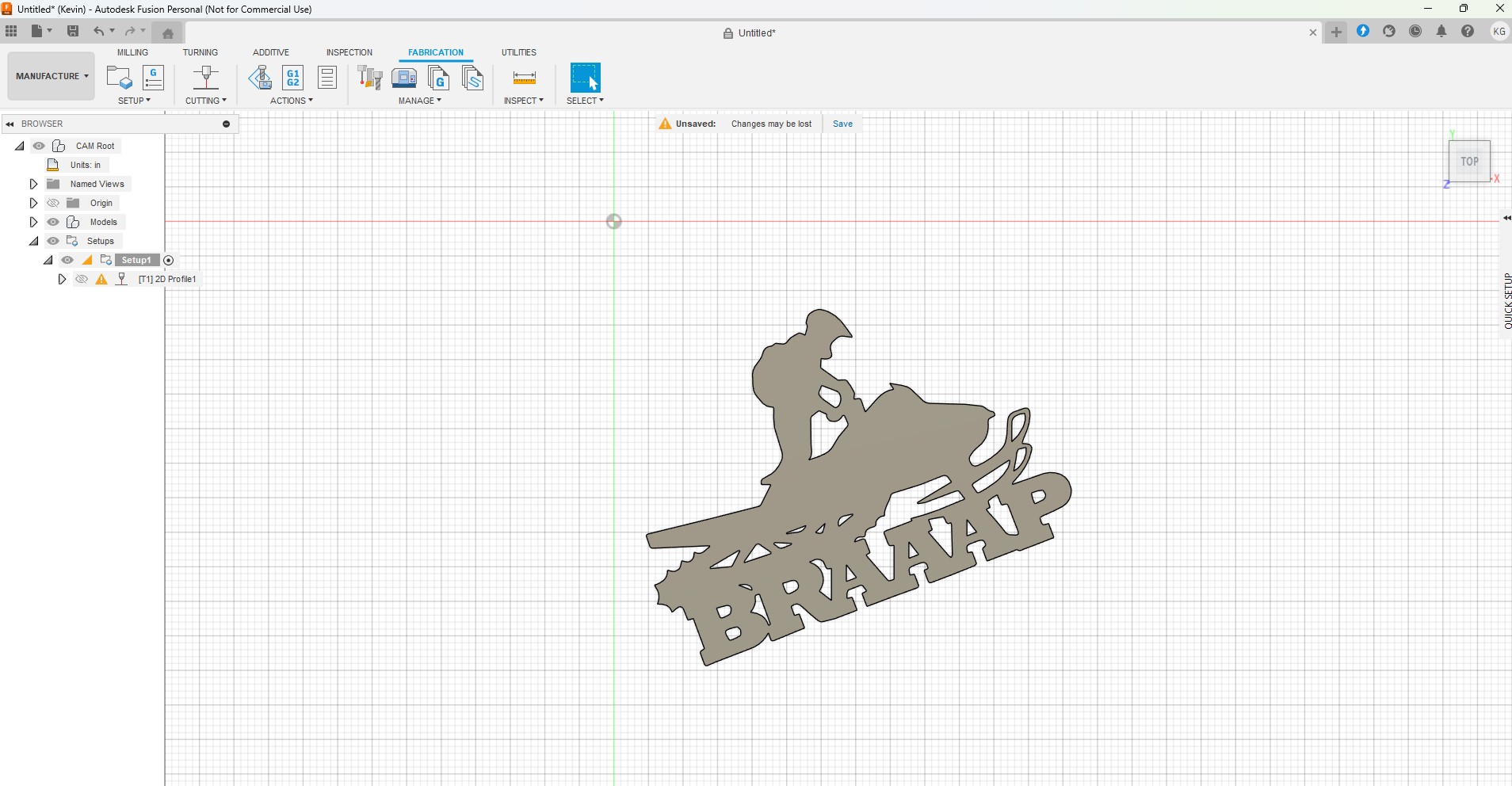
Good evening everyone! I am very new to this whole process and struggled on how to find the answer using the search button because I am not sure how to word it. I imported an image in Inkscape and converted it to svg and extruded it in fusion 360. After the post process finishes there is a few things missing in the image
Looks like it dropped all the small, closed loop features. Meaning your sketch features are likely too small to cut based on the kerf width info in the tool info.
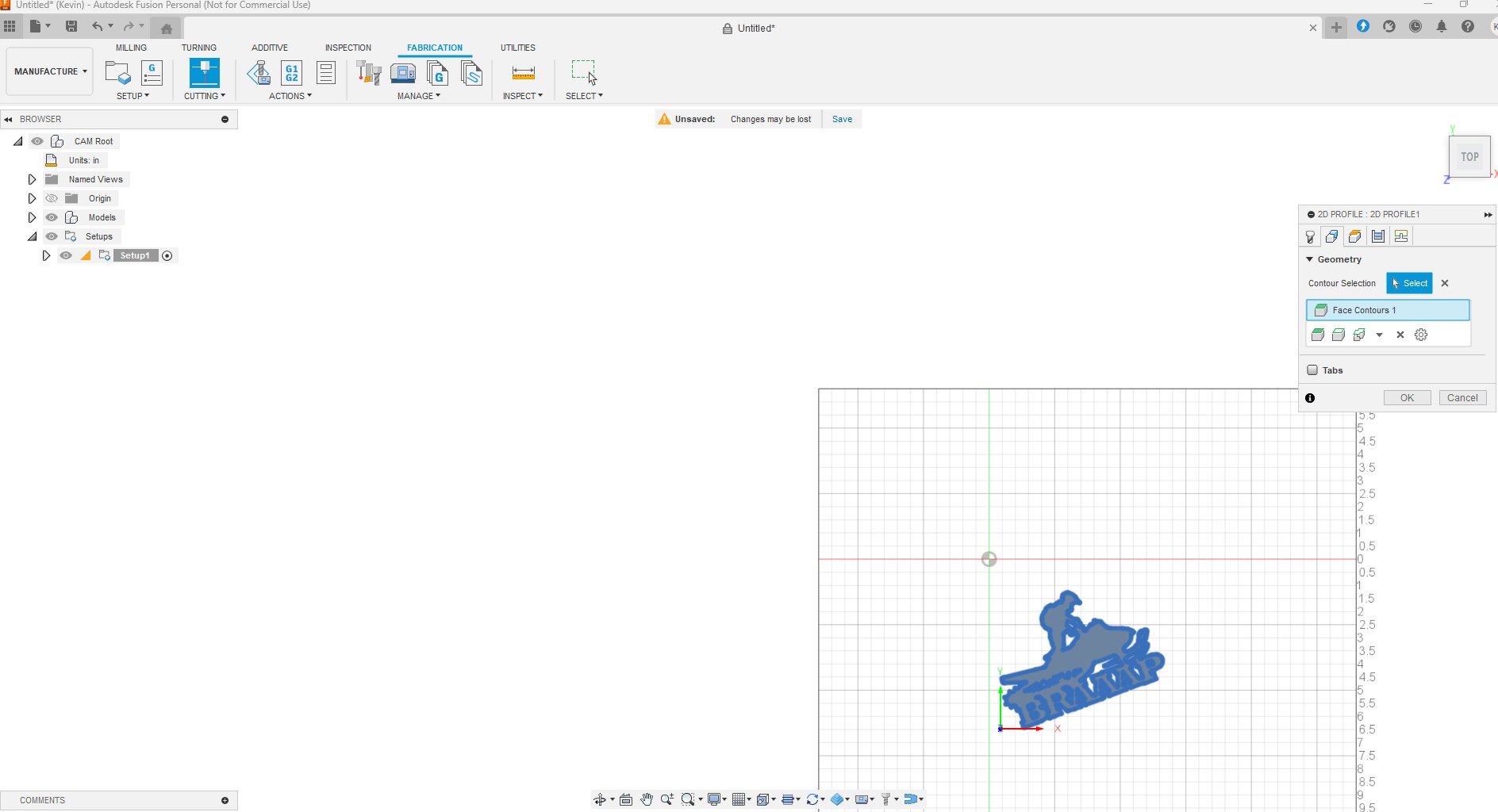
When you created the tool path, did it have a checkmark or exclamation? If no checkmark, it means it deleted features/paths that were too small to cut.
Just try scaling up the sketch and see what happens.
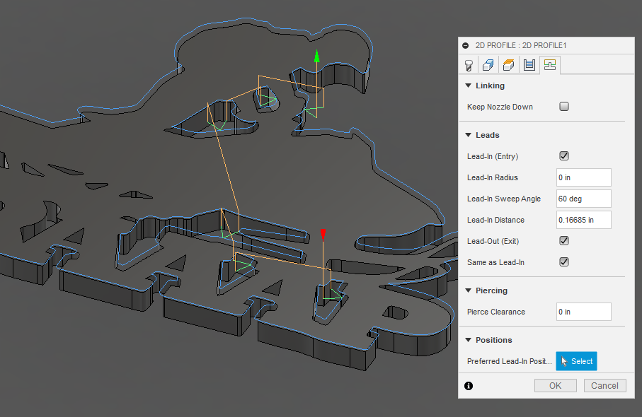
Reduce your lead in length and set your Pierce clearance to zero.
Fusion believes it cannot fit all of lead in lead out kerf with, etc ( all options in the 2D profile menu and the tool menu) into the small openings so it discards those contours
I haven’t had real good luck with importing an SVG file to Fusion 360. Try saving your file as a DXF once you have it sized like you want it. Some of the real small stuff is going to cause problems but there is a way around that also. With you lead in length.
As Jim said post your f3d file, he will help you figure it out.
Another thing you might want to do in Inkscape is enlarge at least the three front small hole for the suspension that are above the R and A. I’m not sure that make since, but I hope so. What is the overall size you are shooting for?
And then just play with your lead in distance like maybe decrease it to something like .1 maybe even .07 for the real small holes. In that case you might want to make two operations one for the small holes and another for the rest of items. That may not be necessary, but you might get a little divot where pierce is depending on your kerf width.
This makes sense as the default image size is only around 6", I tried making it 10" and 12" to see if it fixed anything and it seemed to pick up a few more areas of the image, still not 100%. Thank you for the reply
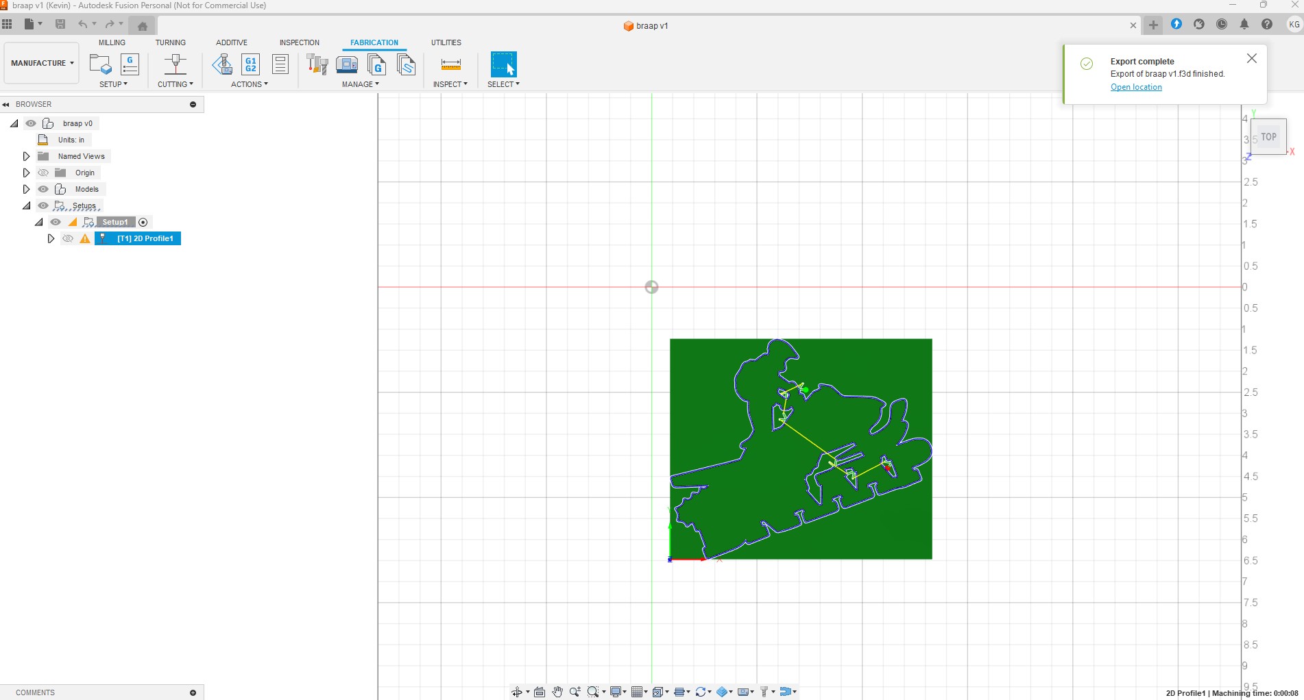
I reduced the lead in a little and also changed the piece clearance to zero, it picked up a few more parts of the image, ill post a screen shot. thanks for the Reply TinWhisperer! I have been through many of your posts since getting on this forum and appreciate the knowledge you share.
Thanks for the reply! I converted it to DXF and imported it that way into Fusion360, everything looked odd to me and the process I was using to post process a svg file did not seem to correlate. I’ll upload the file
Thanks for everyone’s input! I did as TinWhisperer suggested and was able to pick up a few more details of the image, but not all. The image is about 6" but I wouldn’t care if it was up to 10" if it made it work, ill upload the screen shot of what it looks like now, as well as the f3d file.
is this a scenario when fine cut consumables would make a difference if I was wanting to cut the file at 6" ?
(also note I am using a razorcut 45 and I have my setting to 300 ipm because I’m just practicing getting used to the table/machine on a bunch of 24g metal sheets I have on hand)
With your setting, notice the lead-in/lead-out real estate that is required to fit that into the contour without interfering with any of the contour cuts.
If you reduced the lead-in distance to 0.1 and add a finishing overlap of 0.01 to be certain of smoothing out the lead-in with the contour you would pick up some more…but still not everything.
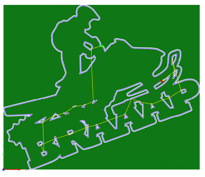
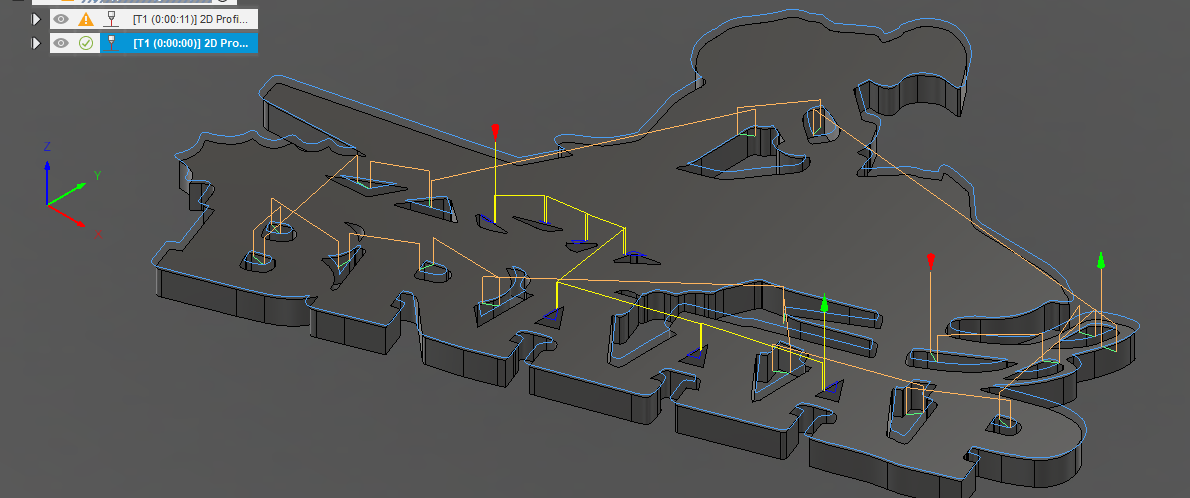
So here I picked “Preferred Lead-In Position” and got quite a few more to take. You will see the white dots that signify where I picked. In some contours it still rejected them so I simply picked another location and left the other mark. Now it is picking up lots of contours but not the smaller ones.
For the smaller ones, I will just need to go ape on them by the suggestion given by Just-4-fun.
I will add a second toolpath and make the lead-ins very small to get those last 7 contours. They would need to be so small in some cases that it is not going to matter so I removed the lead-in/lead-out. You will see that second toolpath in yellow.
My philosophy with tiny or no lead-ins is that “Sure, it might show (will show) a nick where the cut starts but if that is less of a distraction to your work than having the contour totally discarded then it is a necessary step.”
Jim, Thanks for taking the time to explain and look over what I am working on! The point of view you posted showing the depth of it helps understand the lead in / out area issues. The second tool path is also a new one for me, I will mess around with it more and try to cut one!
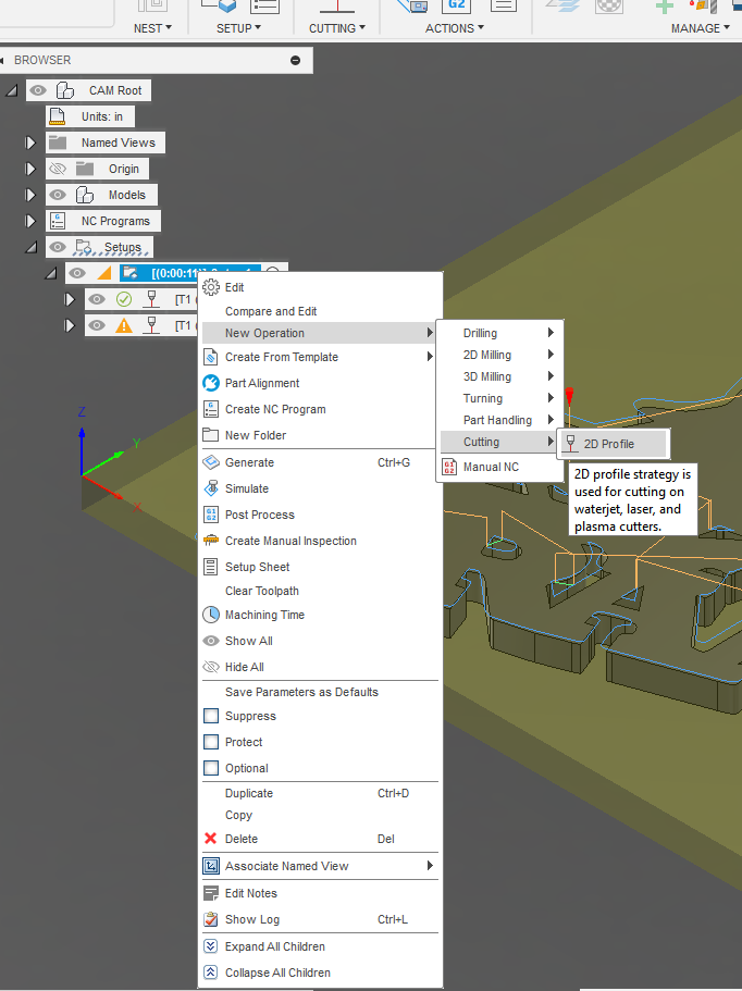
If you decide to use additional toolpaths, I think you will like it. Here is a quick path to adding them:
Right click on the Set-up in the browser, left click on [New Operation]>[Cutting]>[2D Profile]
Pick the same tool, if you have the Hobby/Personal version as the gcode will fail by design since multiple tools are not allowed in a single set-up unless you pay for the subscription.
You will want to move the additional toolpaths ahead of the toolpath that cuts the perimeter of your piece otherwise the main cut will free the main part of the design and it will allow the plate to shift and/or lose connectivity to the work lead.
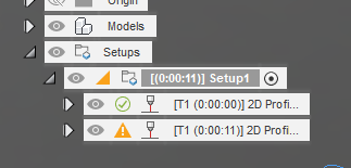
When you go to the final step of post processing, make sure that only the Setup is highlighted in the browser tree. If any of the toolpaths are highlighted, that will be the only thing that ends up in your gcode file.
I suggest we change this topic name considering it has nothing to do with extruding.
It’s the classic “discarded due to linking constraints” from the 2D profile menu issue.
And for future readers if you search the word “discarded” in the magnifying glass above there will be a hundred pages of further explanation of this issue.