I used a bunch of different widths and marred it down to this as the best cut for my big signs on 16 G steel. I’m now using fine cut but it still works great on them. I did a test today at the book specs at .46 and it was ok on my 3inch test piece. So not sure what to do?!
Cut a square, measure it, if it’s the right size, keep the kerf setting. If the square it too small, change the kerf setting by -1/2 the difference.
I don’t know what kind of lead in Fusion uses, but I use arc lead in with Sheetcam.
A perpendicular lead-in/out is about the same as a Fusion 90 degree entry. The arc is like the Fusion 45-60 degree entry/exit. The tangent one doesn’t really have a directly comparable one in Fusion.
I only use the perpendicular entry when the piece doesn’t have enough room to support an arc. An arcing lead-in is easier on the machine when the torch slides into the cut vs having to take a sharp turn as is the case of the perpendicular type.
Great I will do that! Thanks
1 Like
Cool I will set to arc! Thanks
Great detailed answer, I’ll know what to use and when to use it, thank you so much!
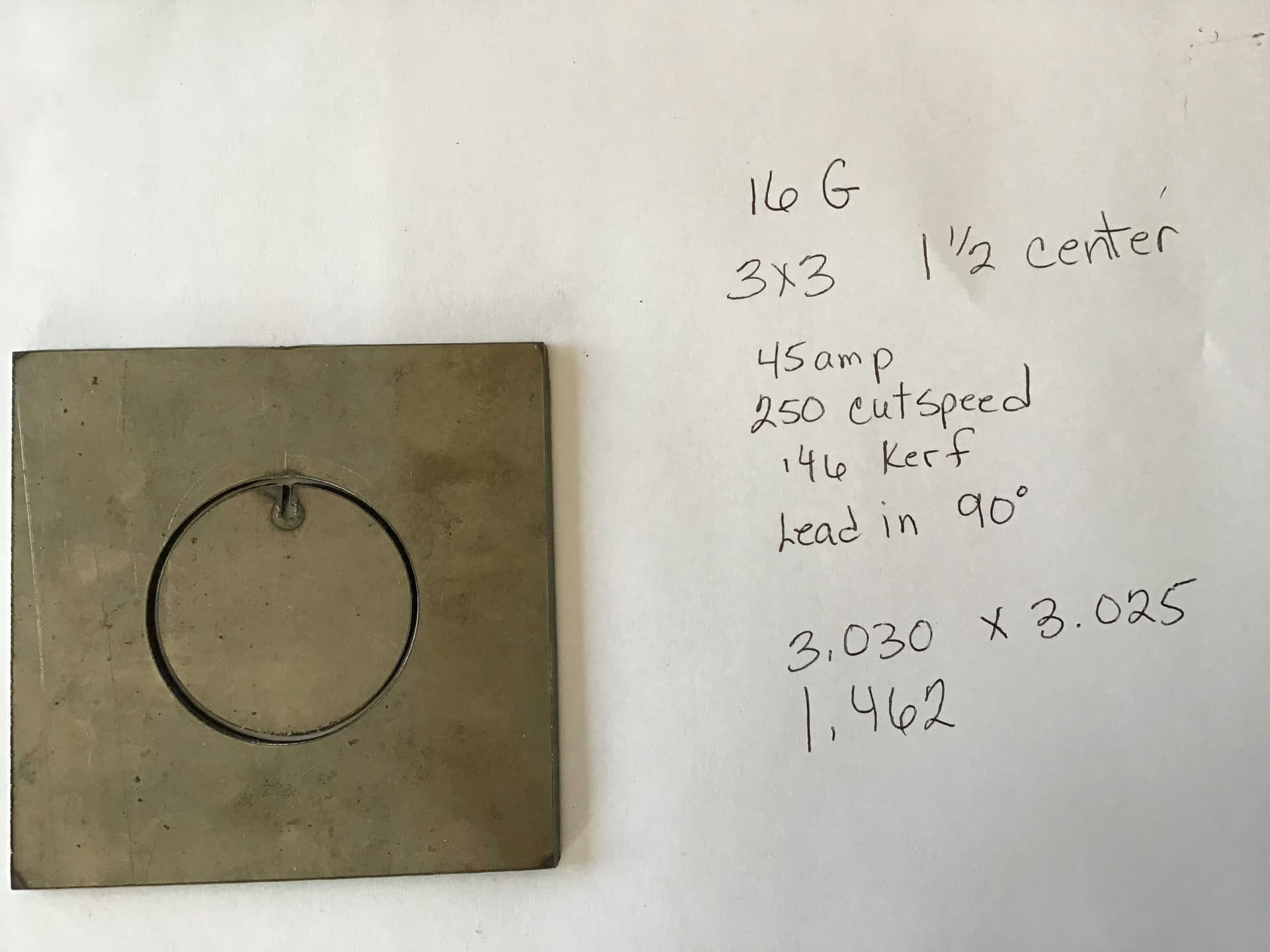
Hey everyone, I did a test cut to make sure what the kerf actually is to set up sheetcam. This is what I came up with. I’m just doing art so nothing to precise at this point. Your thought would be greatly appreciated.
A square (or rectangle) will give you more accurate read on size.
Yes the squares are 3x3 and cut at 3.030x3.025
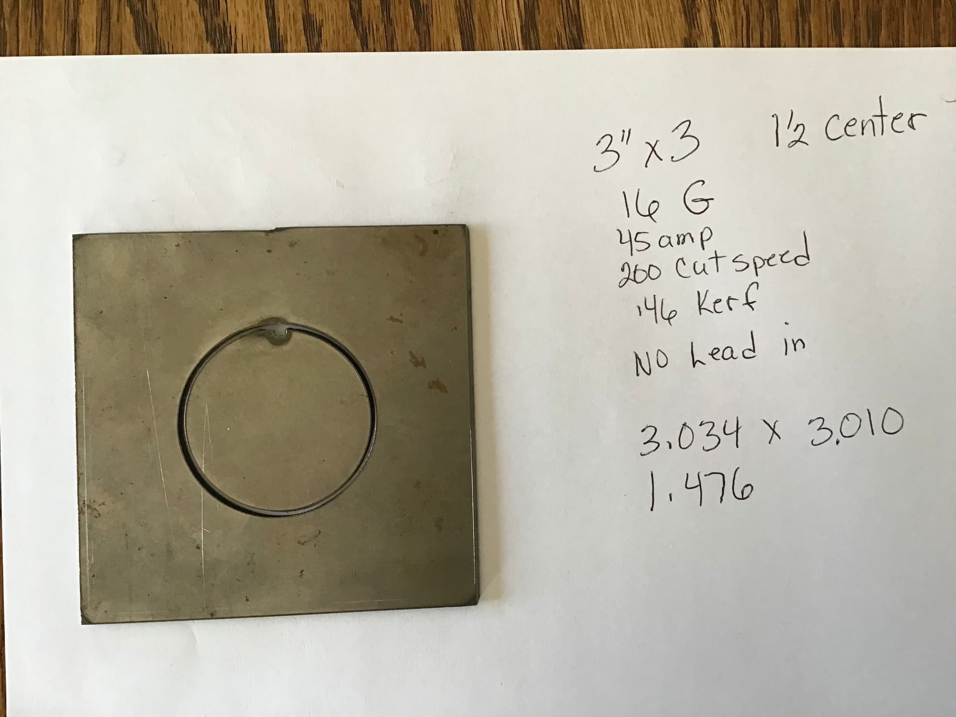
The other one cut at 3.034x 3.010
Ah, I TOTALLY missed the squares. All I ‘saw’ were the circles… doh!
Thanks.
Since your cuts were outside cuts, a larger shape than target means that the CAM program is offsetting too far from the correct cut line. Therefore, I’d reduce your kerf setting by half the average error (0.0275/2) ~= 0.014. or 0.032" kerf (assuming your ‘0.46’ kerf mentioned above is a typo and it’s really set to 0.046". If your kerf is really set to 0.46" then I think you’ve got more problems than simply calibrating kerf ![]()
It did occur to me that, when I calibrated my system, I did a square within a square. So, 2" square cut as an inside cut and 3" square around that cut as an outside cut. That gave me a good kerf reference on both sides. The resulting ‘wall’ (if the squares are centered) should be 1/2", but that also includes a positioning error in the equation, so measure just the widths and heights of the inside and outside squares.
In your photos above, it looks like there was a shift in Y during the cut. Check for looseness in your Y leadscrews (this is typically the stops that press into the bearings on the ends. They need to be firm), or some looseness in your Z Ways. Another thing could be drag on your torch cable causing a twist in the torch.
1 Like
Haha no worries, Thanks I will check all this out when I get home today! Hmmmm .046 or .46  I need to go look at that again!
Well I’m an idiot! No need to agree with me though  it is .046 not .46 at almost a 1/2 inch! all this is just running together in my brain! (Or lack there of!) tomorrow is a new day right?!
2 Likes
hey tom or anyone, i have a question about lead in speed if im cutting 16G steel at 250 or 200 should i slow down the lead in? I have a very very small nick and dont know if the is because the lead in speed is to fast or is that just the nature of cutting?
I haven’t seen a way to change the lead in feedrate in Sheetcam. It is the same as the cut speed. I haven’t found a way to make the mark at the start/stop point disappear. I think its just a fact of plasma cutting that there will always be some artifact at the start/stop point. I have had parts laser cut in the past and they also leave a mark at the start/stop point.
thanks David! i figured that it was just going to be there.
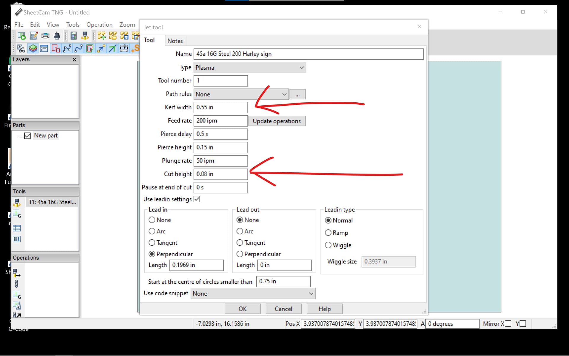
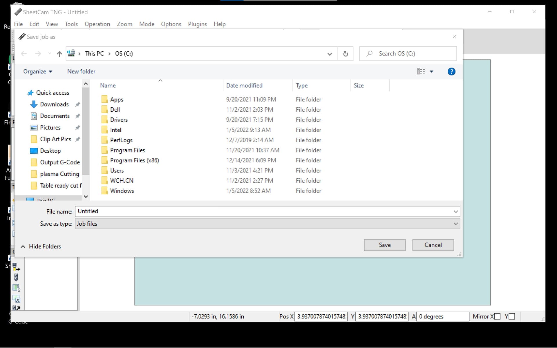
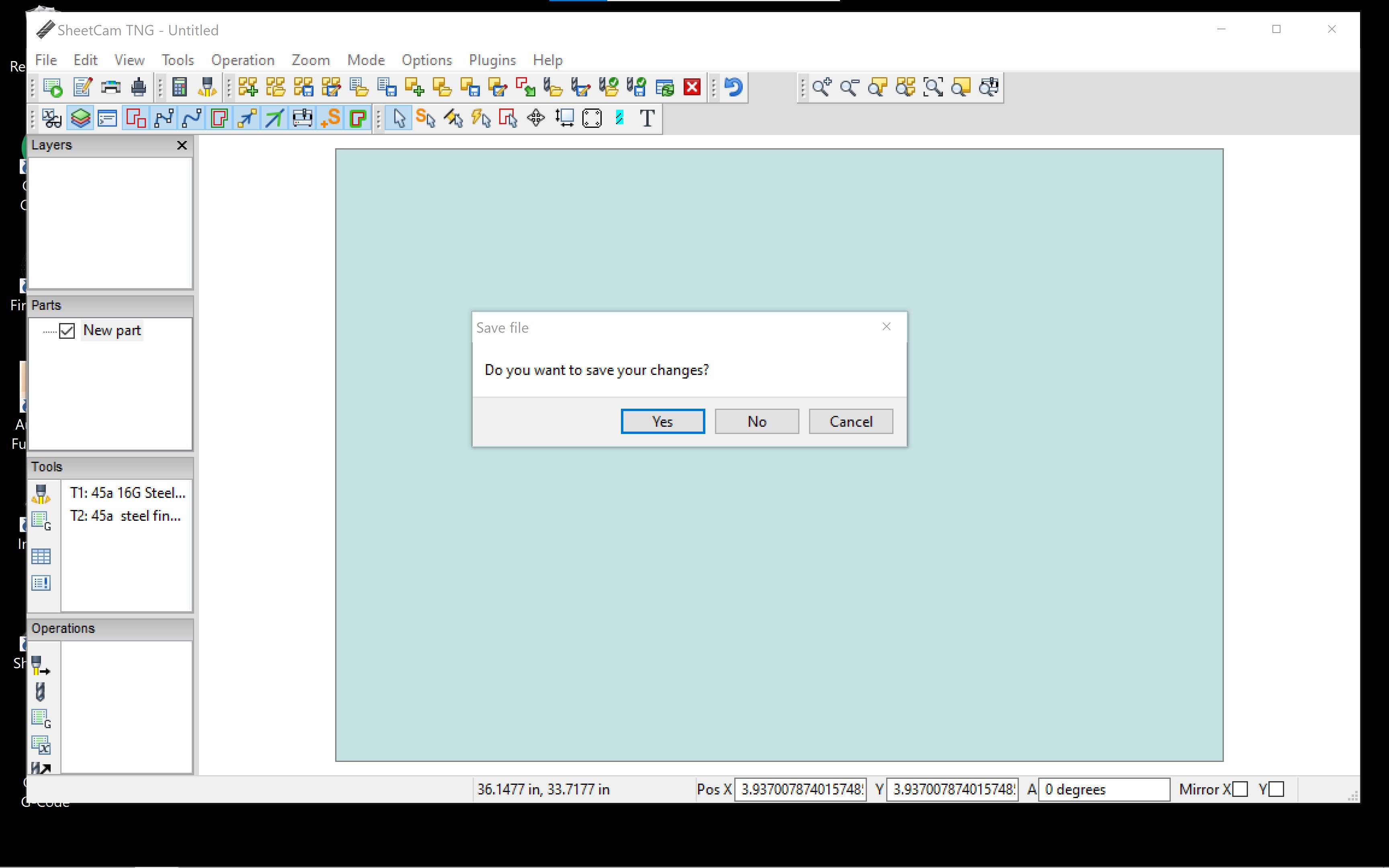
I have changed my settings in this tool and hit “OK” when finished no matter how many times i change it is goes right back to the wrong settings pointed out in red. I even tried to save changes and this window comes up??? that is the OS so why would the tool save there??? I thought fusion was confusing! ![]() now trying to learn sheetcam!
now trying to learn sheetcam! ![]()
You can’t change the speed, but probably don’t want to. I recommend an Arc lead in and lead out, which reduces the rate of change in direction as the cut approaches the cut line. I typically use 0.250" on both lead in and out except on heavier materials that I rarely (never) cut. You could try a slight overcut as that will allow the torch to travel past the lead in point which has been heat hardened. Unfortunately I forget how to do that 
1 Like
You can choose the location where you save the job files, just click a different location on the left hand side. It just automatically goes to the last location that you had open.
Have you tried clicking on “update operations” before hitting OK on the tool? I have had this happen if I try to change the tool after I have already set up a job, but not if I change the tool with no operations set up.
In the jet cutting operation window, there is a box for “overcut” and you can input the length of overcut you want.