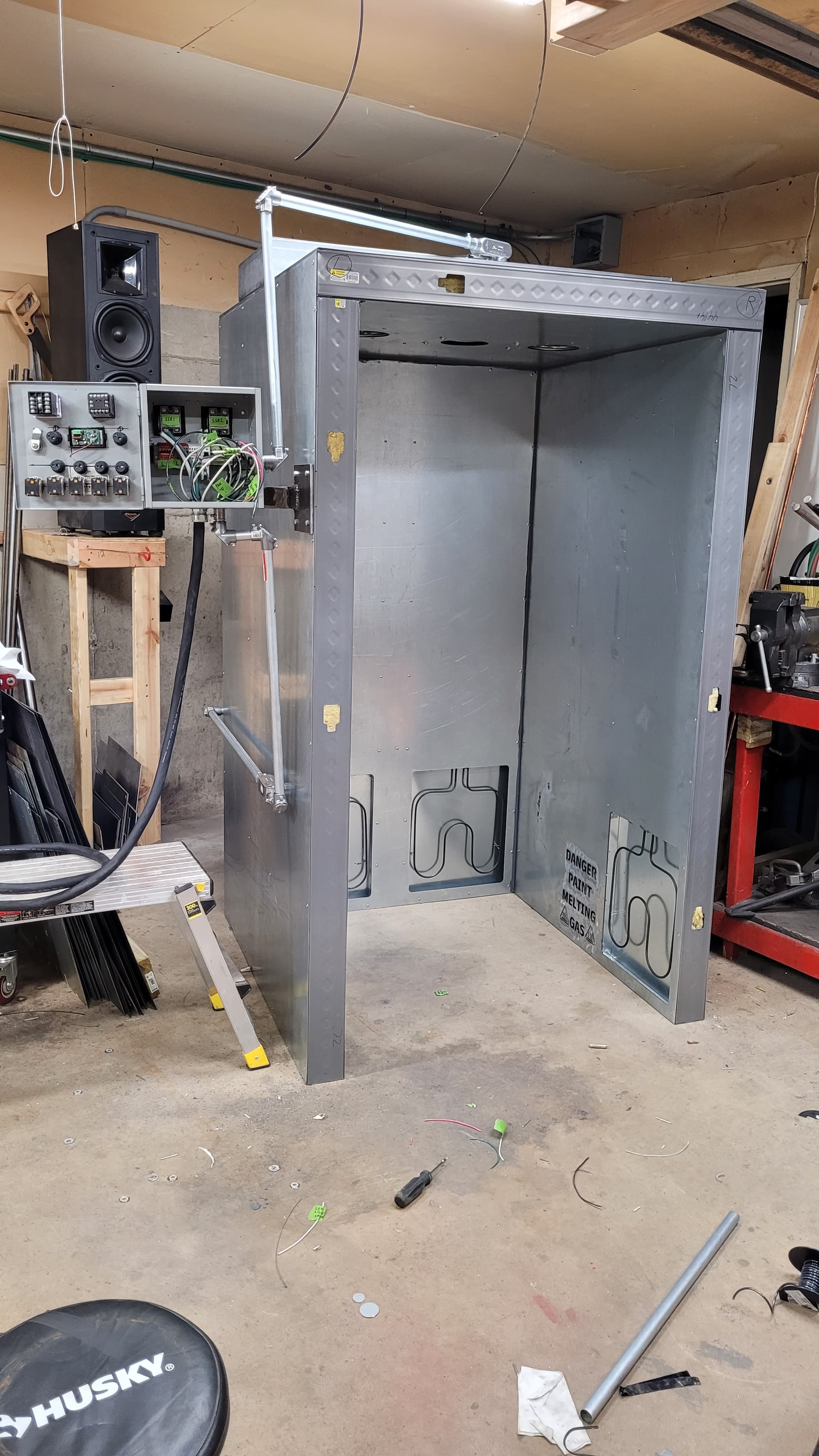
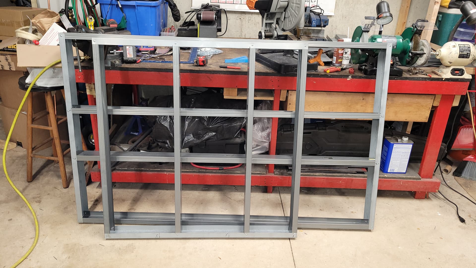
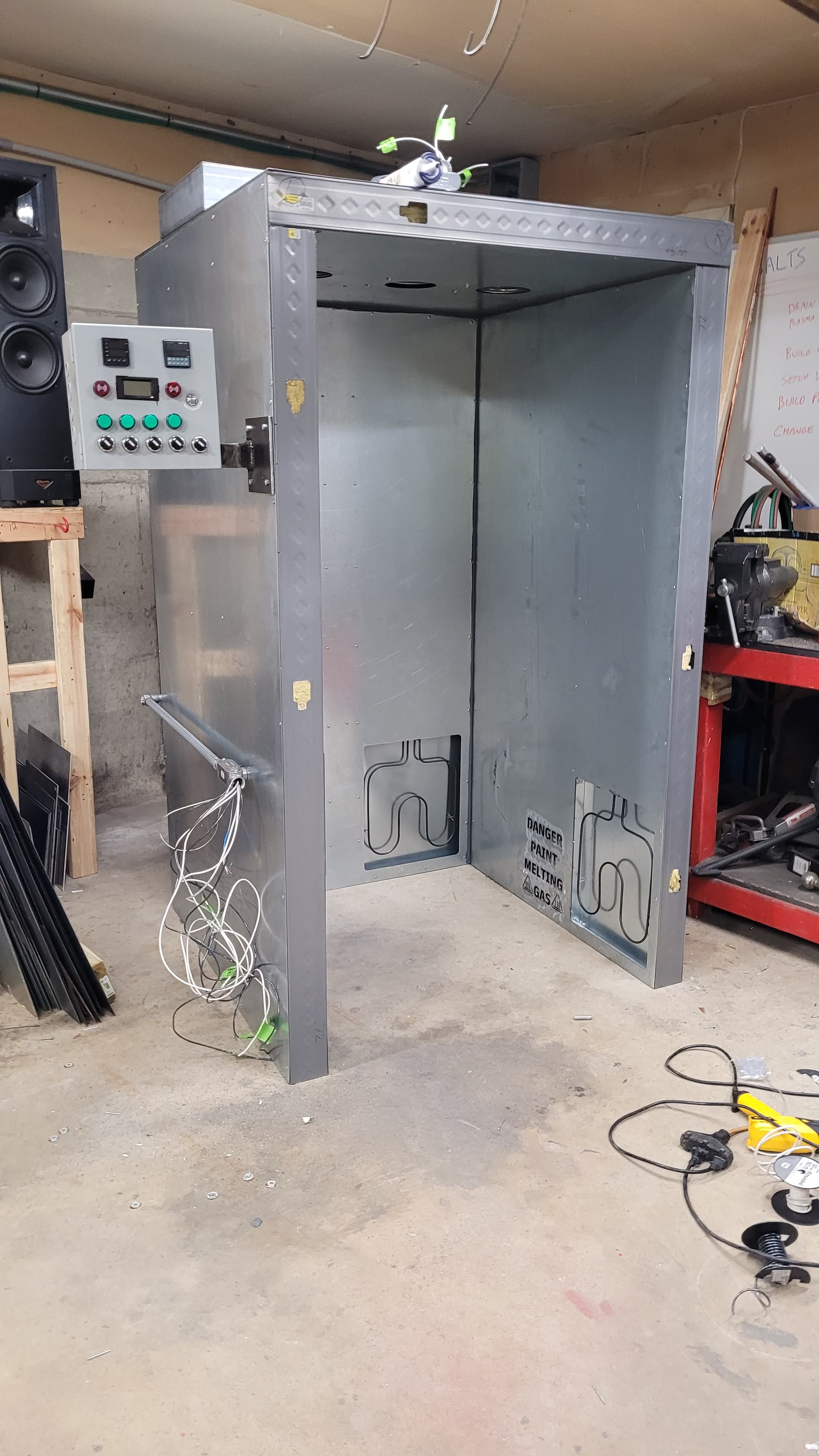
I’m tired of stinky rattle cans every time I finish a sign, it’s time to move up to powder coating. I bought a Columbia Coatings Hyper Smooth 3.0 (a nice mid-level powder coating gun), now that I have the cart I need the horse. I read the article posted on powdercoatguide and it was very thorough so I figured what the hell I can do that. The oven I’m building is very similar to the one in that tutorial with a few modifications. The oven internal size is 37"x37"x72" which is big enough for anything I can cut on the crossfire pro, or lawn mower decks or motorcycle tins. I’m building it from scratch and so far I’m into it for a little over $2k but I believe I’ve finished buying all the parts. Luckily I found a great deal on Craigslist for the sheet metal, unfortunately it’s 17 gauge galvanized so it’s VERY heavy and I had to wear my PAPR when I was cutting it. The framing is done, the oven is skinned, the door is built, insulation is done, basically all I have left at this point is installing the door and building the control box and wiring at the control box. I’ll update with pictures and videos as the project moves along. I believe I will be done with it this weekend but I said that last weekend and the weekend before…
Anyhow, if anyone has any questions/suggestions I’m all ears although I’m nearing the end stages of the build so making changes from here on out is going to be limited to the control box. I uploaded Part 1 of the build to YouTube last night but I rushed the video because I needed to clear up space on my hard drives for more videos…I have roughly 1200GB of videos for this build so far. The next videos will be a little better.
Almost forgot, I’m making it expandable since the number one piece of advice I got ahead of time was
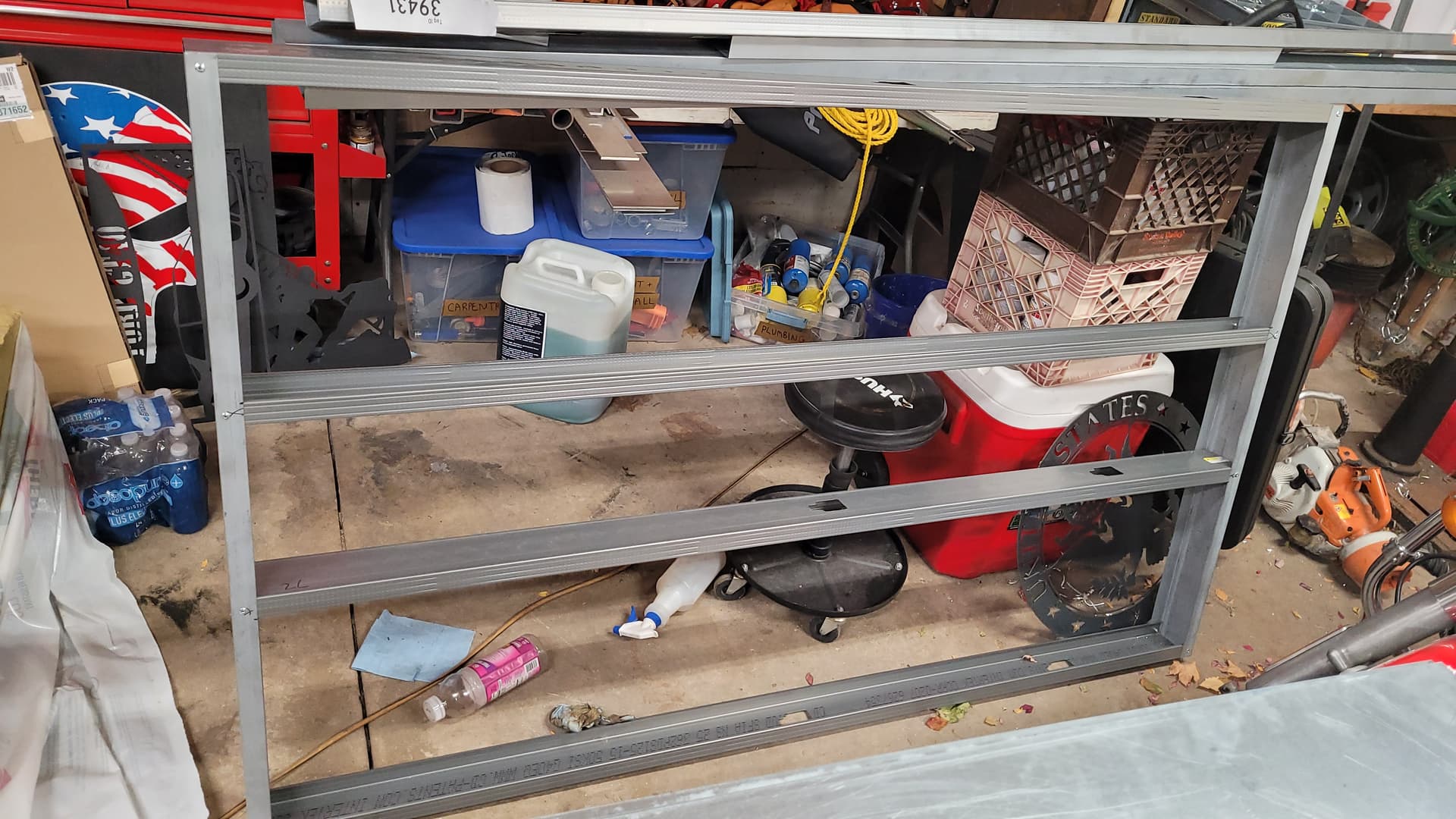
“whatever size your planning to make it, make it bigger.” Also I’m building a shelf that will cut the interior size of the oven in half for when I don’t need the whole oven to increase efficiency.
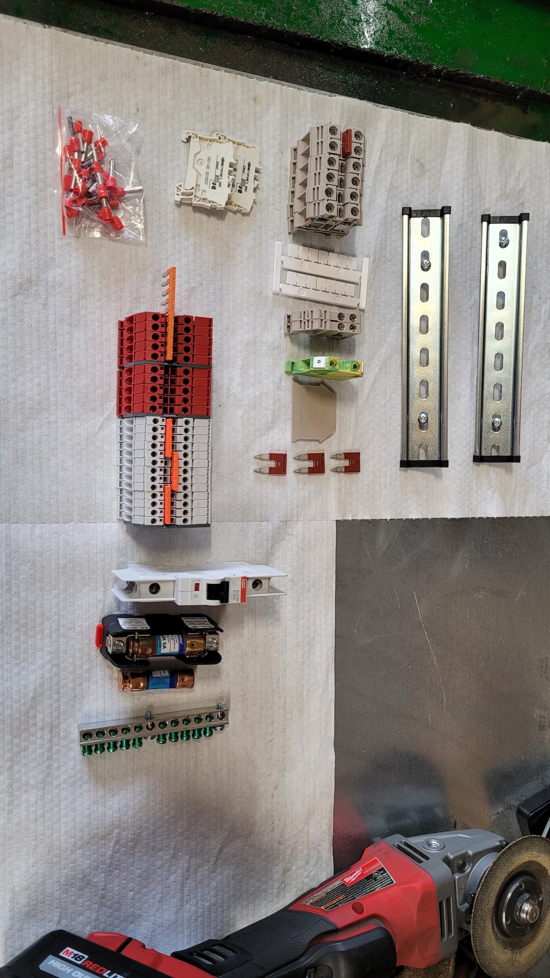
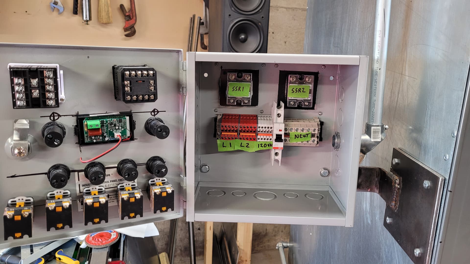
I spent another $75 today, bought the power cord strain relief (the cord is just a 25’ Primeweld welder extension cord so it’s really beefy), and a whole mess of DIN terminals and a DIN 15A breaker for the lights and blower motor. I honestly think that’s the last of what I have to buy. When the oven is completely done I will make a detailed list of all the parts, fasteners and materials and add it all up for a final cost. I got all the wiring run to the control box today from the oven and I installed all the DIN hardware and power cord. Tomorrow I will draw out the schematic for the wiring, I have Friday off so I’ll wire the panel Friday, hang the door Saturday and hopefully melt some paint by Sunday.
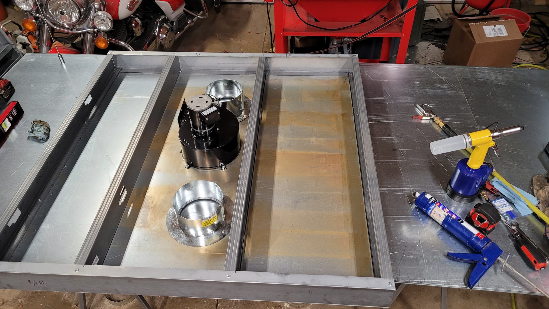
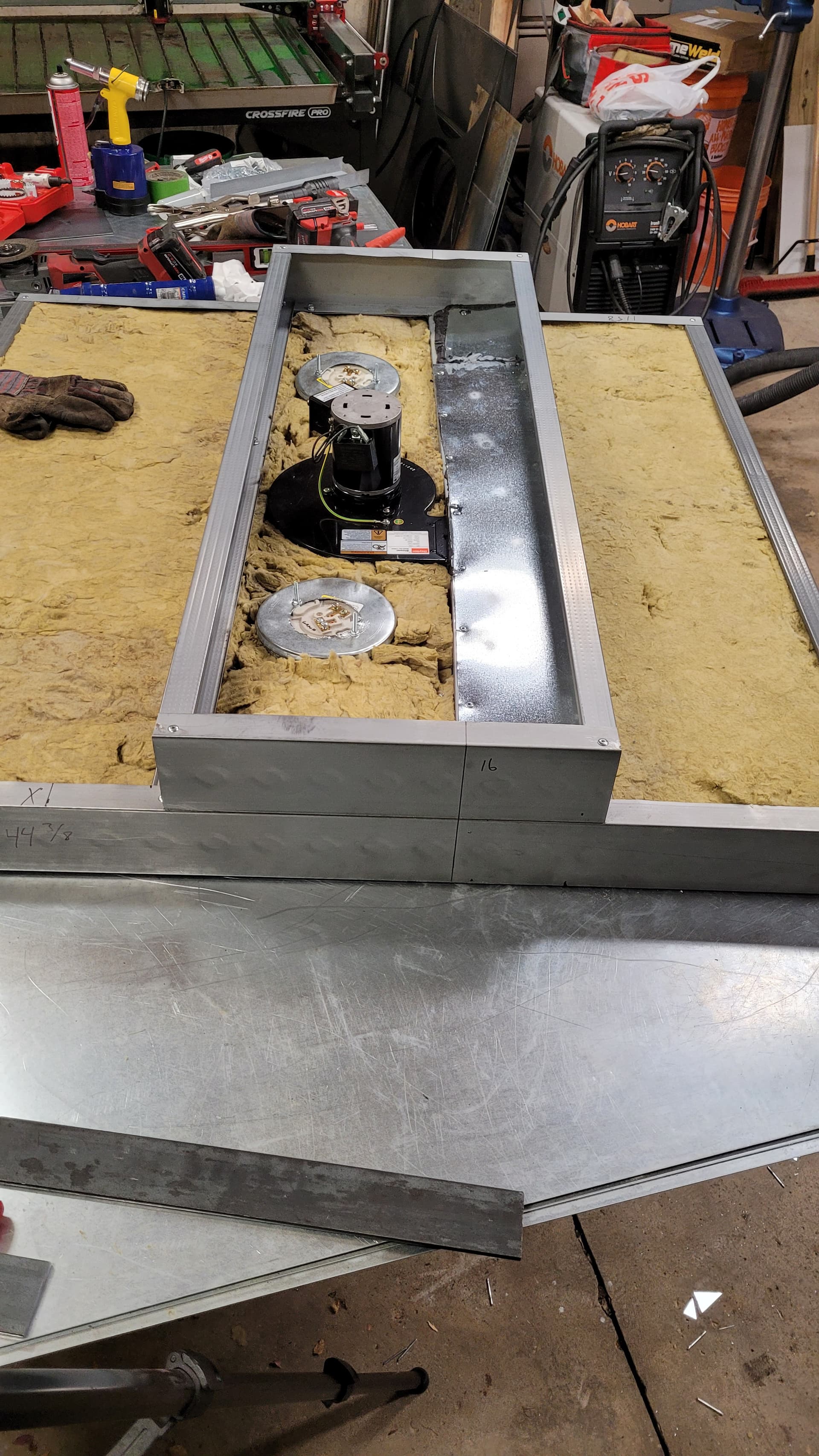
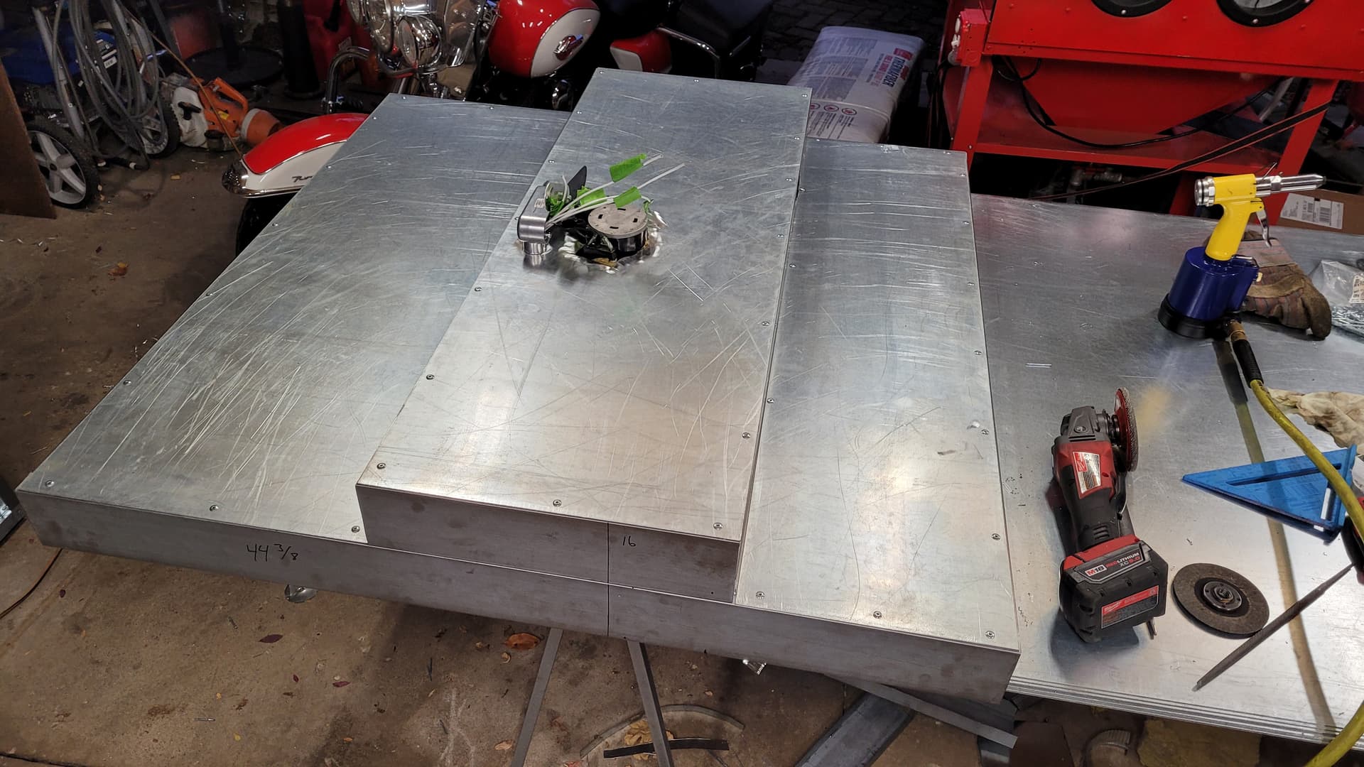
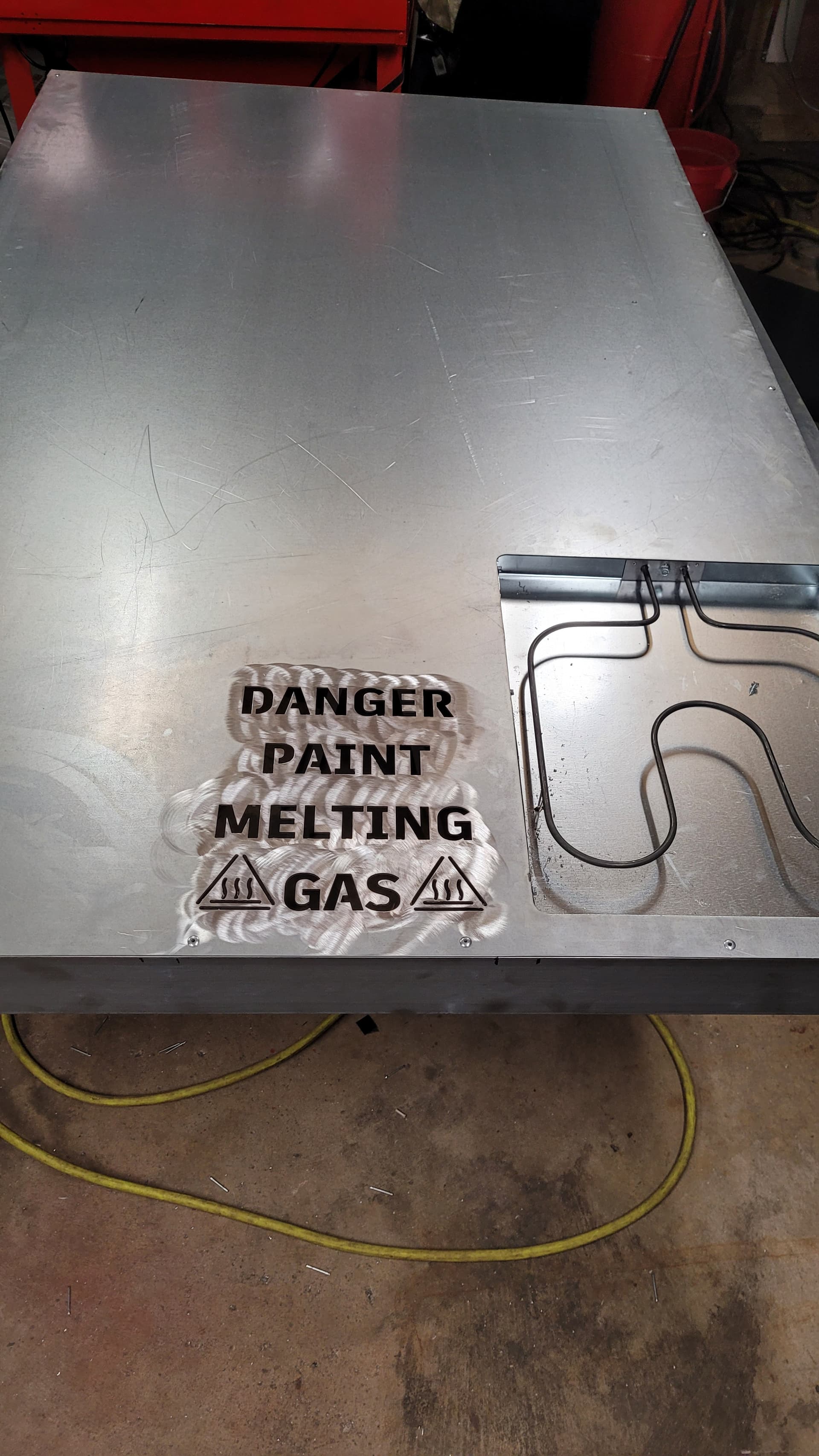
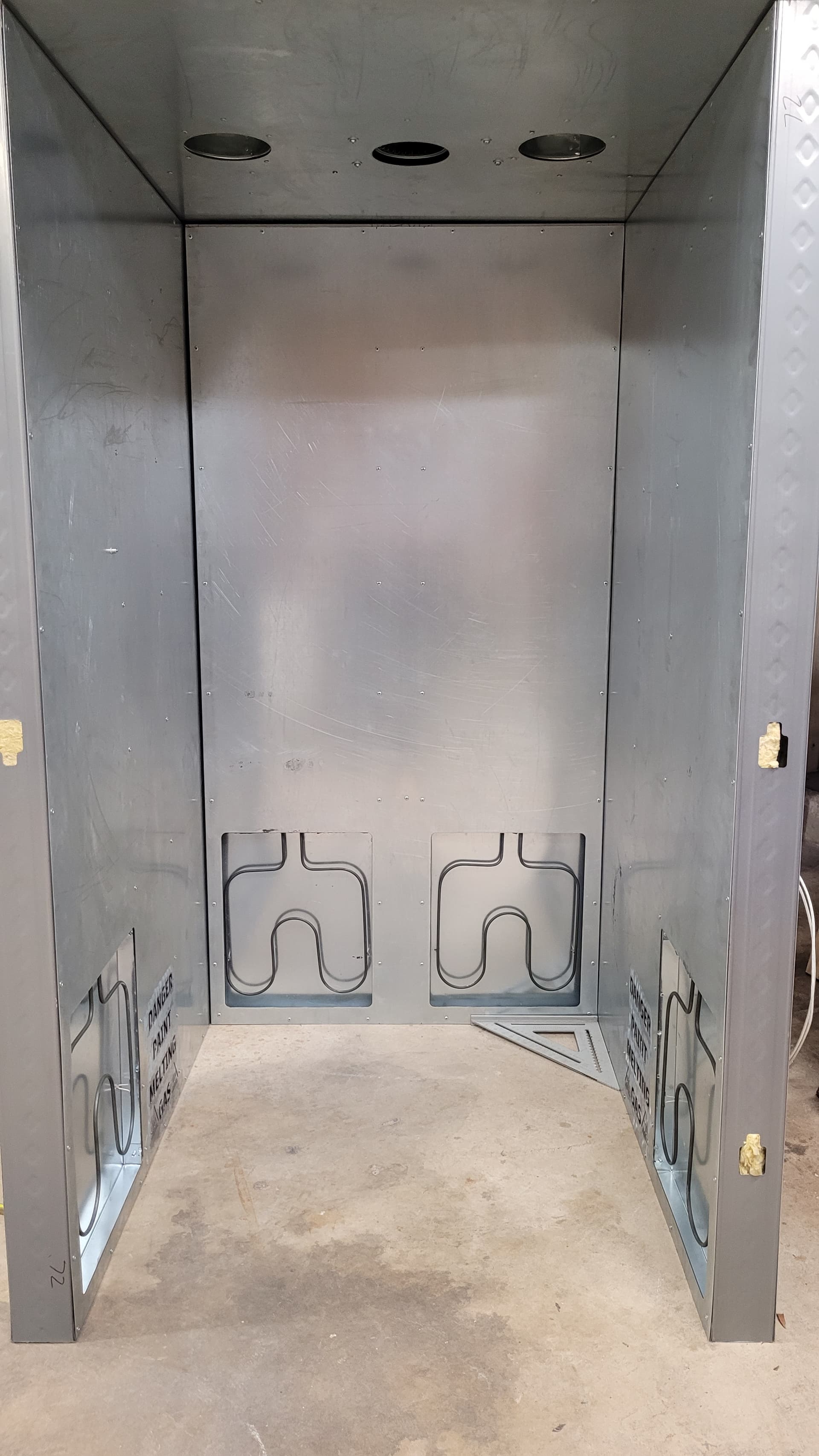
One cool feature I added to the oven, the blower that circulates the hot air picks up in the ceiling and runs down ducts in the walls then exits through the letters at the bottom of the wall near the heating elements. I mean we have really cool plasma cutting tables for a reason…why use boring vents?
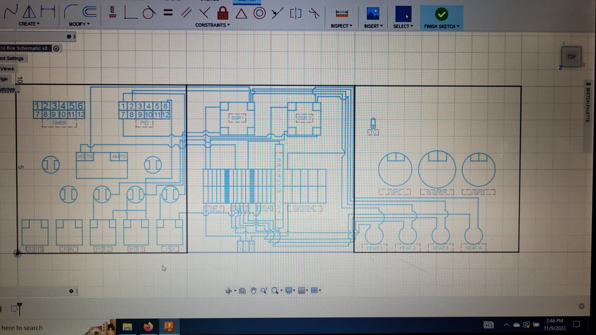
Finished the schematic today and started on the wiring after work. It’s getting there, I might actually be hanging the door on Friday and cooking paint on Saturday although I do still have to build a paint booth.
I couldn’t help myself, I laid out the schematic in Fusion…made some changes on the fly
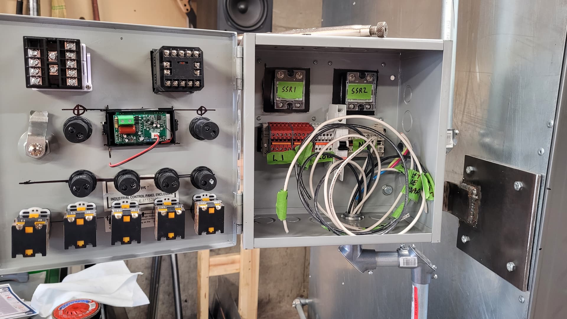
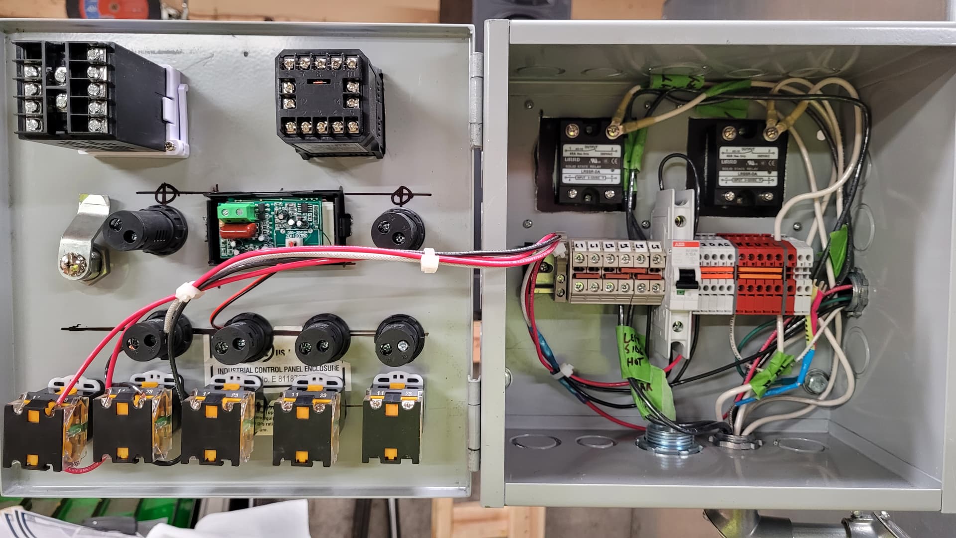
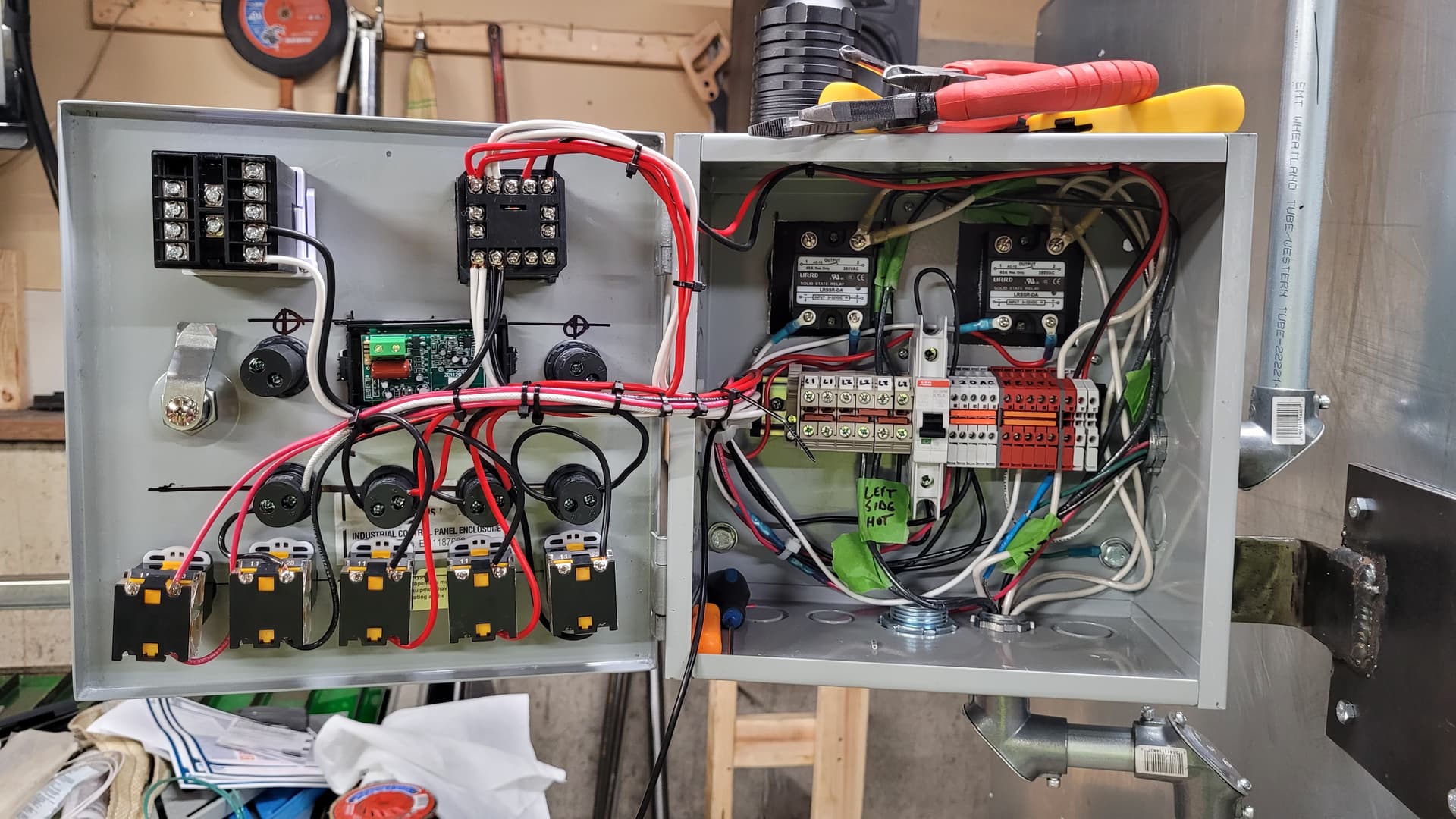
I will do the cable management when everything is wired, it’s kind of a mess right now but it will get a little better at the end. Going to need to pick up some cable stays/wire looms.
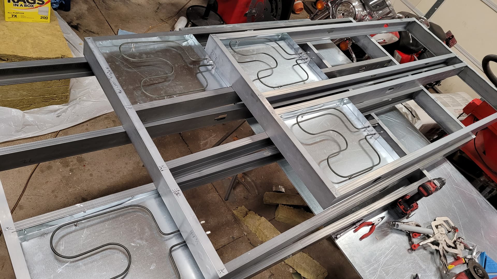
I did use high temp stake ons for the heating elements! Had to special order them, I don’t think they made the video but I think I have a pic of them. Difference maker, they slipped right on. It would have been embarassing to have to pull the skin off the oven because heat shrink terminals were burning…
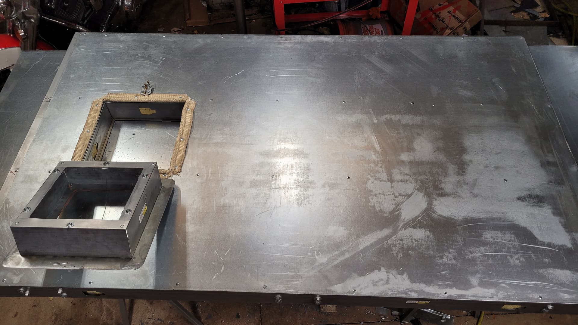
PS I forgot I have to skin the door jam, I did reinforce it with 1/4" steel plate but I want something smooth for the tadpole gasket to seal against.
Something happened to my first post and the YouTube video of Part 1 stopped showing so I fixed that. If you haven’t seen Part 1 it’s at the top of the thread in the first post now.
I ran into a question mark that you might be able to help me with. I’m wiring in the indicator lamps, should I run them in parallel or series with the switches? I initially wired them in series but that would require the full amperage of the blower motor and the lights to run through the LED indicator lamps and I think that would blow them out. They should still work in parallel right?
Thanks, I’m rewiring them now. The indicator lamps and alarm buzzers are the only things left to wire. I should have it plugged in shortly. Poor word choice…
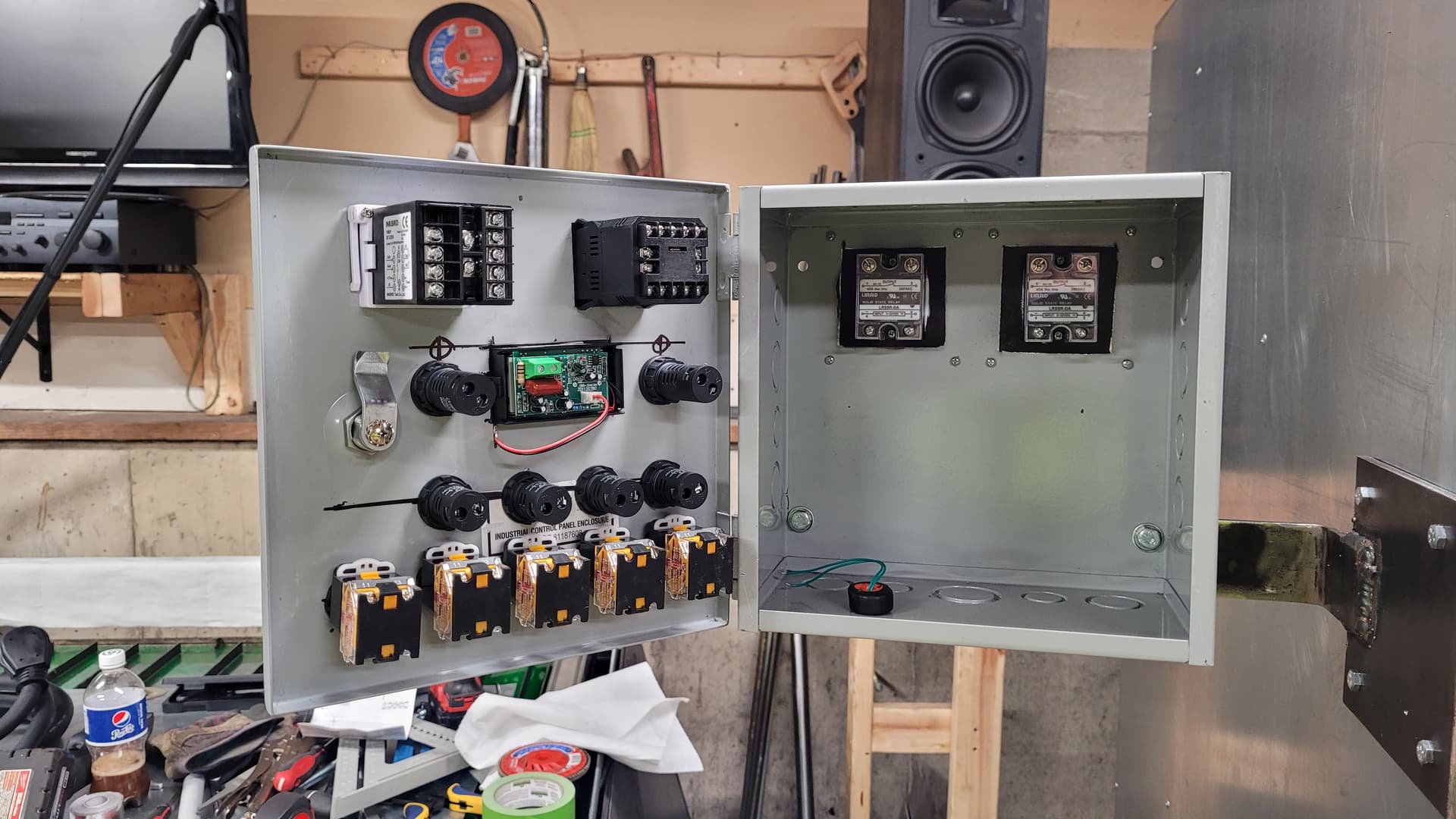
I have screwed something up in the wiring for the heating elements. I fired the whole thing up and only one of the two elements on each SSR fires up, also the two indicator lamps for SSR1 and SSR2 are both dim compared to the other indicator lamps. The two elements that do fire up go full hot, I’m not sure where I’m losing the other two elements but I’m sure the dim indicator lamps are a symptom of whatever that issue is. Each element is getting full time hot from line 1, SSR1 and SSR2 each gets hot from line 2 and sends that current when the SSR is engaged. SSR1 sends its current when it is engaged to the left side and right rear heating elements, SSR2 sends its current when it is engaged to the right side and left rear heating elements. Currently only the left side and right side elements glow. I am running the SSR output from the PID to the rotary switch on the panel, to the indicator lamp, to the SSR. There are two problems I think that I need to find, one is why only one of two heating elements per SSR is heating up and the other is why the indicator lamps are dim. Other than this the panel seems to be working great, the Voltage/Amperage gauge works perfect although it’s showing low amperage because only half the heating elements are turning on. Also the timer and PID seem to be functioning just right. I haven’t programmed either of them yet but I don’t think that would cause the heating elements problem.
I have an idea on the heating elements, if I got a wire switched between the two back wall heating elements they won’t turn on because there will be no way to complete the circuit. Basically I would have Line 1 hot on both sides of one heating element and Line 2 hot on both sides of the other heating element. That would prevent them from firing up, gonna disconnect all rear heating element wires in the panel and run continuity. Fingers crossed…
I was right about the rear heating elements, I got two of the wires reversed. Switched it up and now all heating elements work perfect! Also I think I figured out what’s wrong with the indicator lamps, the ones that are dim are running off the SSR output from the PID which is low voltage DC and these lamps are meant for 120-240VAC. I’m going to try grounding them to the other SSR terminal instead of the neutral AC terminal block.
")