I would like to use the marking feature of my Hypertherm 45 XP. How do I create a marking path in F360 based on a file? I have created a tool file and a cut file, but I’m wondering how to set it up without lead in and lead out. Has anyone worked with this, or do you know of a tutorial on how to do it.
2 Likes
Here is a screen shot walkthrough.
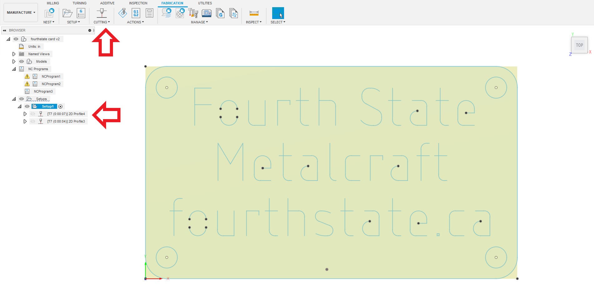
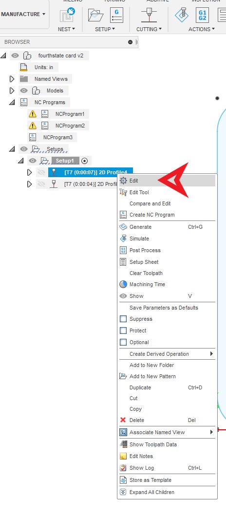
Edit tool path info here
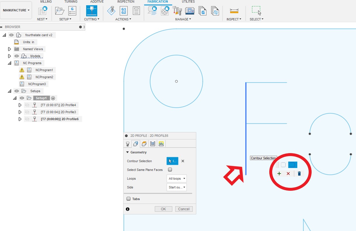
double click line to mark and this little box will pop up

single click the rest of the line to add in to the path by hitting the green plus. now repeat till all the desired content has paths
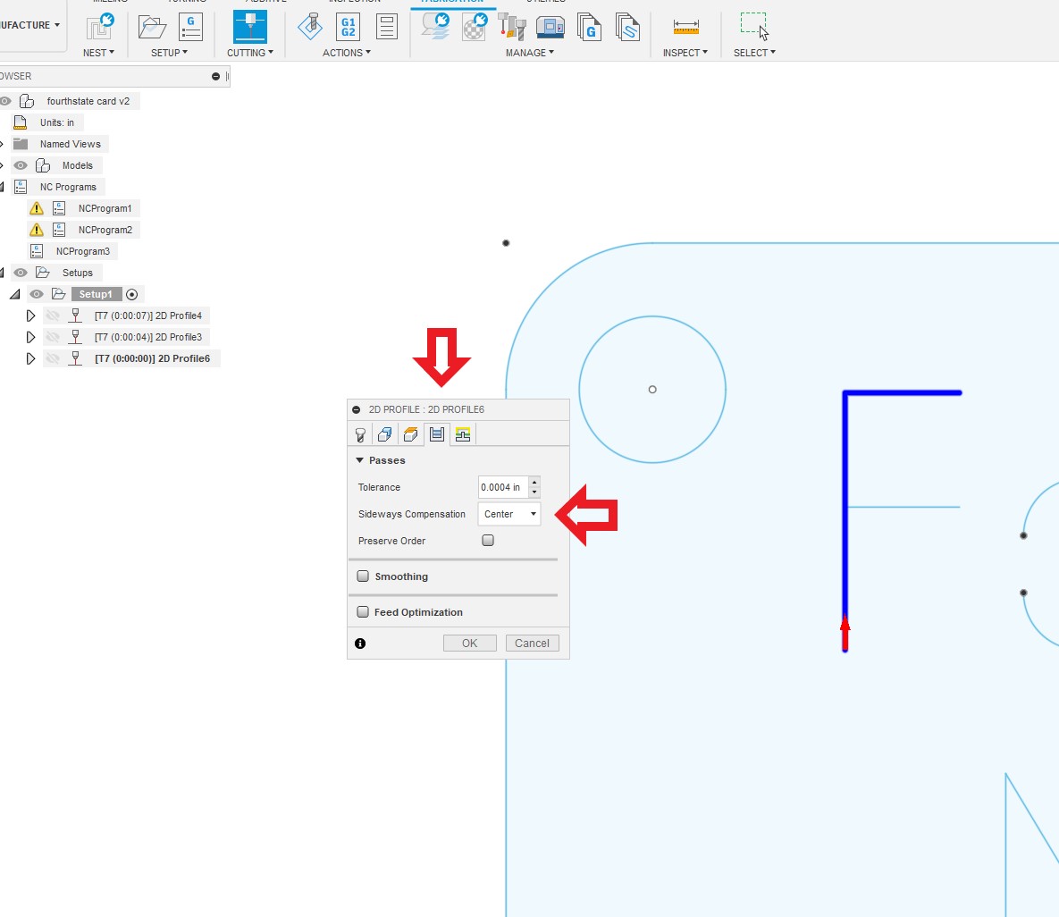
select passes tab and set sideways compension to center

uncheck all the lead in options and set pierce clearance to zero

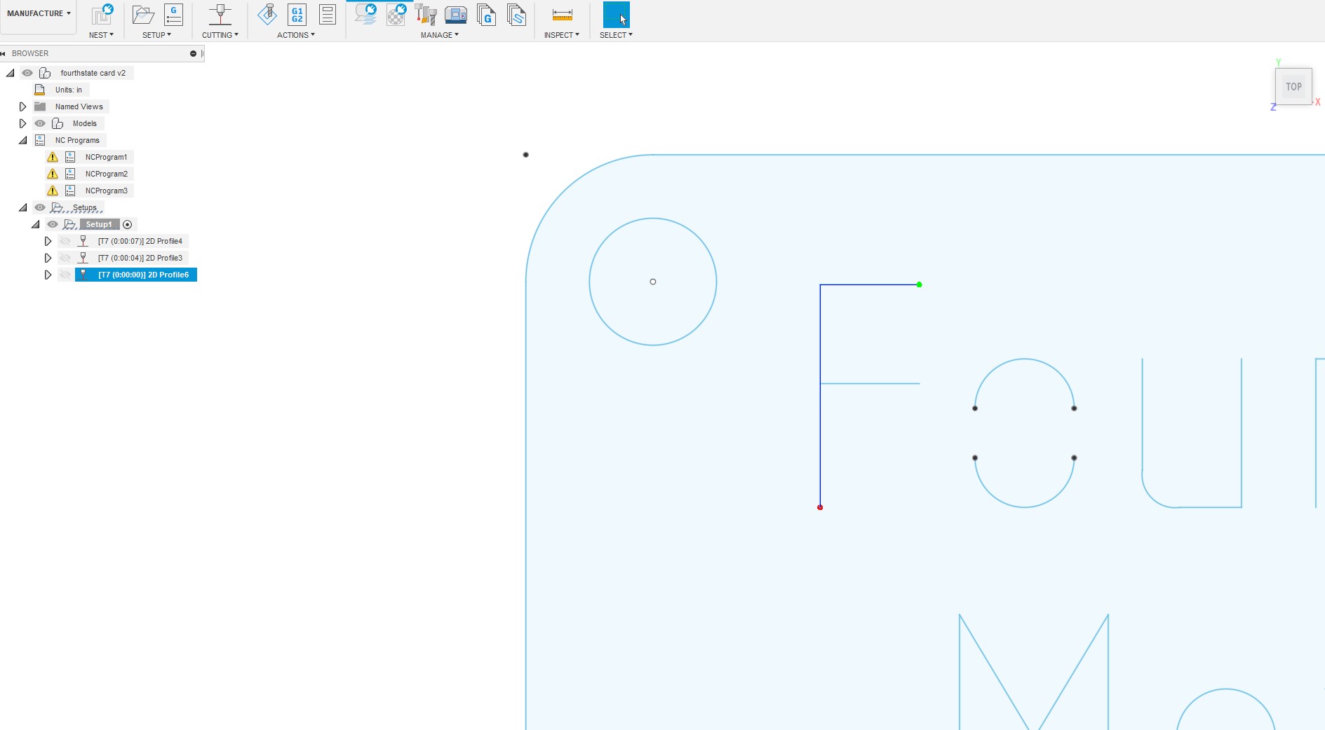
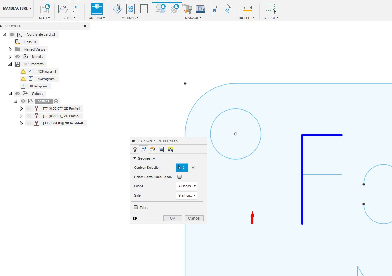
there is the selected path green dot to red dot along the blue line.
2 Likes
Thank You TinWhisperer! This is just what I needed.
1 Like
Thank you for sharing this.
1 Like
You are very welcome. I have recently started a series of fusion 360 videos with audio .
There’s any topics you’d like a future video to cover please post it anywhere on this forum with a @TinWhisperer or PM me.
Have fun cutting.
good of you to take the time to do this it will certainly help out people new to fusion 360. I do have one question as you are only cutting letters with one pass. Have you figured out how to minimize blowout at the end of the cuts. When I first started cutting single pass letter I had blowout at both ends. After adjusting lead in and not using the recommended pierce delay and height I now have lines which start nice and clean w/o blowout. However all the ends are blownout to about 2.5 mm
Thanks,
Z
So which end?
The beginning of the cut
or
the end of the cut?
You’re right about adjusting the Pierce delay down that’s the way I got rid of my start of cut mark.
Also I make sure I have a piece of sacrificial geometry or cut that is the first cut before it starts my actual piece.
1 Like
Just the ends. I even attempted a few gcode modifications including turning head off before retracting, also decreasing cut height, etc, etc. Still blows out the end. For parts yes I do as you suggest without issue. It is only for single pass letters I have the issue. I now keep several samples around to show people. And advise if we increase letter width to 4mm I can make the blowout holes go away .
Thanks,
Z
1 Like
Could you take a picture of what you’re talking about on your samples I’d be very interested in seeing it.
I want to see how the difference between 2 mm and 4 mm effects it
After reviewing my cuts I need to revise 4mm down to 2.71 4mm. I started at 4mm and worked down to what looked best that I could achieve. And while the kefir is quoted at 0.055in / 1.379mm on 14GA my actual is 0.0748in / 1.9 mm
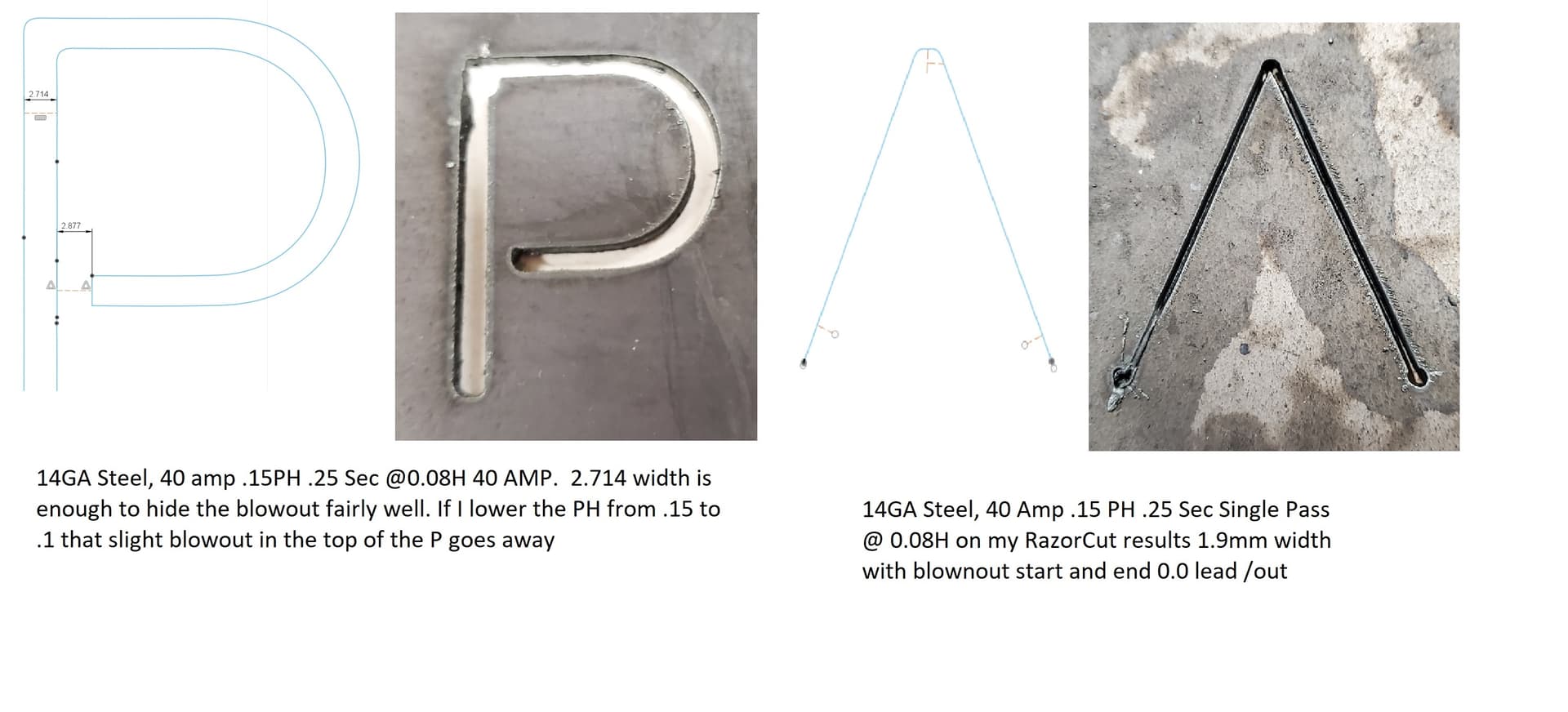
I see one is a single line pass and the other is not.
try to slow down your cut speed on the single line pass and that will increase the kerf width.
You maybe able to increase the kerf width enough to match the pierce mark width.
What is the finish height of the P and the finished height of the A ?
sorry I should have noted that.
P = 1.41"/36mm speed 72 IPM /1828mm (based on the 2nd cut chart about 10 post below the first)
A = 2.36"/60mm speed 221 IPM (based on the first cut chart I found here.)
By slowing down your goal is to get the kerf width closer to the start and end holes?
exactly, you can not decrease the pierce size any more because of the latency of the torch ON/OFF relay circuit but you can increase the kerf width by cutting slower. You maybe able to find a balance that works for you.
1 Like
Thanks Tin!
1 Like