If you have your drawing in Fusion 360, it could be as easy as just moving to “Manufacturing” by clicking on the first Menu item on the top row which probably has the word “DESIGN” there now:

or you may want to change your drawing into a body by pressing the hotkey “E”, this menu comes up and you click on the part that you are making into a body:
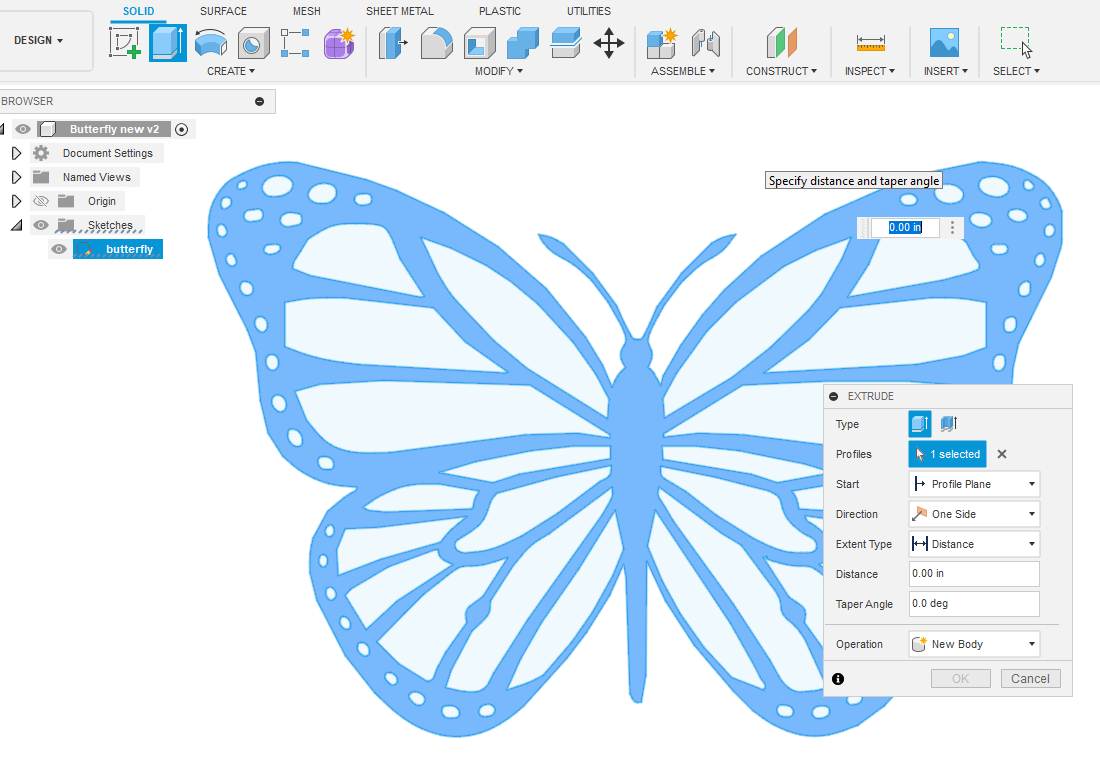
Enter a dimension for the thickness of the body. Here I put 0.125. Doesn’t really matter for this demonstation what size you pick but that is the thickness for 1/8" steel.
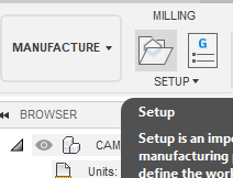
In “MANUFACTURE” space, you will pick “Milling Setup”
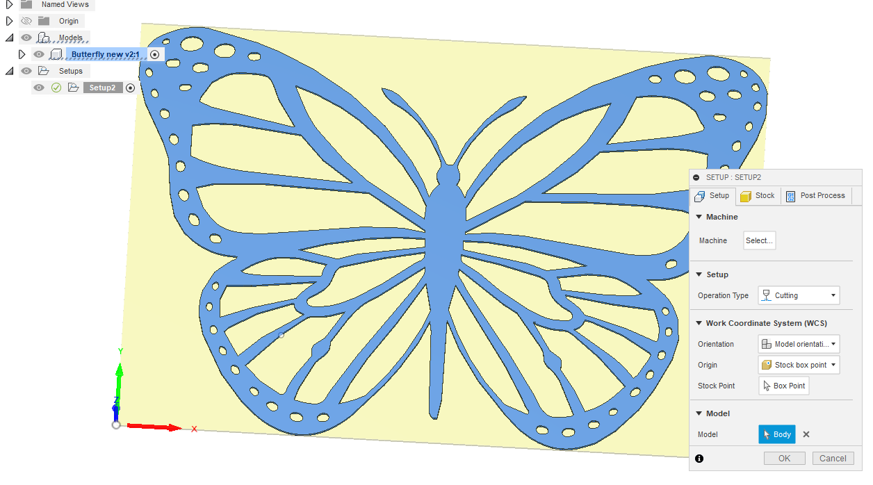
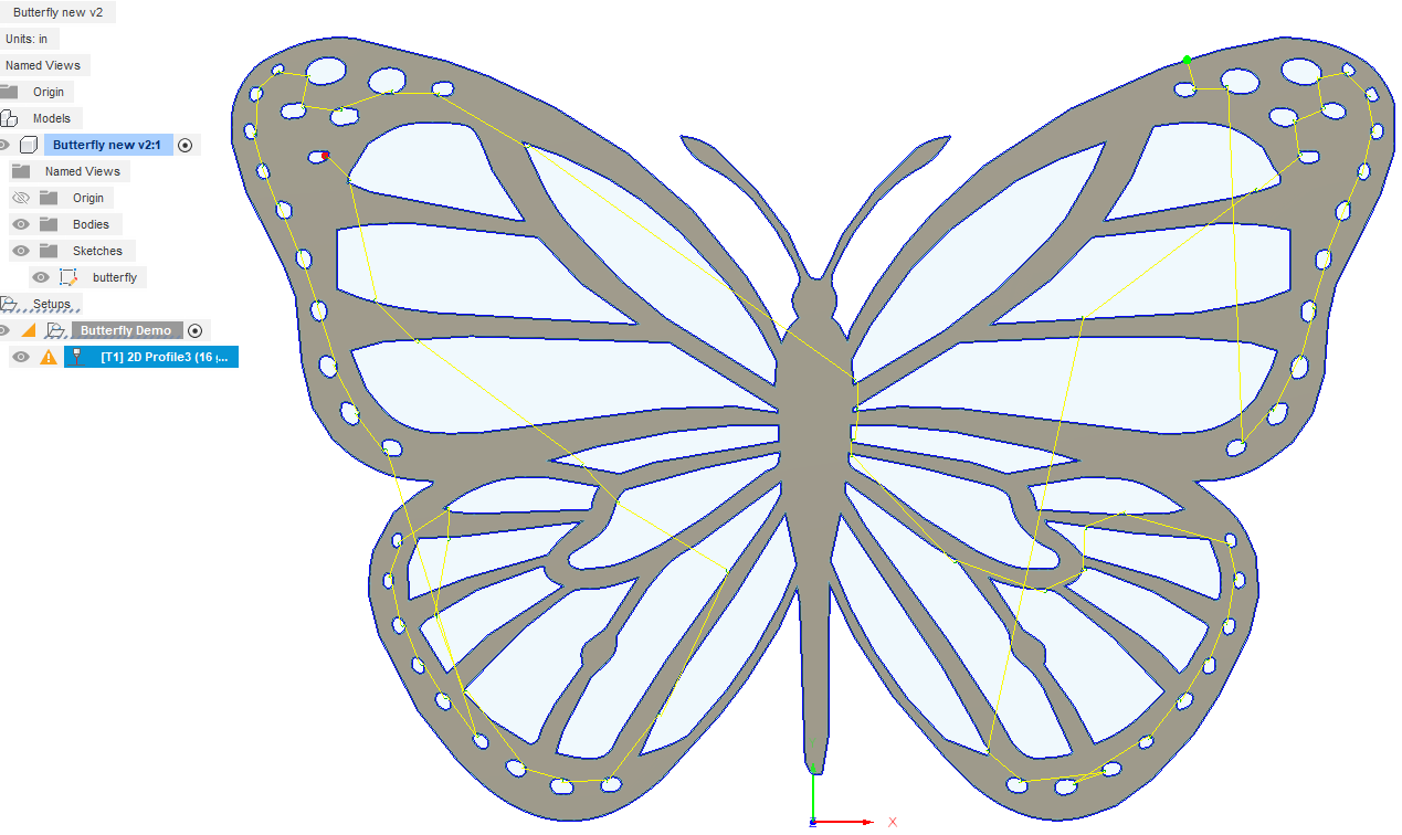
It brings up this dialog menu. You need to interact with the first and last tab but only for a few items: Pick the box point location. I change it from the center to the bottom left. Then it wants to know what is your “Model”. It may have already picked something for you such as “sketch”, which is fine in most cases. You can choose “sketch” by clicking on “sketch” in the file tree on the left.

Or you can pick the body by clicking on the “body” image.
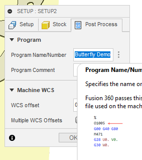
The last menu of “set-up” has you name the “Post Process” file. I put in “Butterfly Demo”
Now you move to toolpath. (Hopefully, you have a “tool” set-up. There are numerous examples of how to set up tools (including in one of the Langmuir Fusion 360 videos). Suffice it to say you need to include your name for the tool, cutting speed, lead in speed and kerf width. That is the bare minimum that is needed.) Now, moving on to the tool path:
I clicked on “Turning - cutting” on the top menu bar. That brought up the toolpath menu consisting of 5 tabbed sub-menus. On the first tab I click on tool and select my tool from my library.

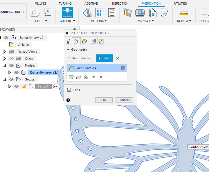
At this point I move to the second tab and need to pick the contours. That can either be by picking the body face:
Or I can use the drop down menu to pick sketch and then picked the sketch on the menu tree on the left:
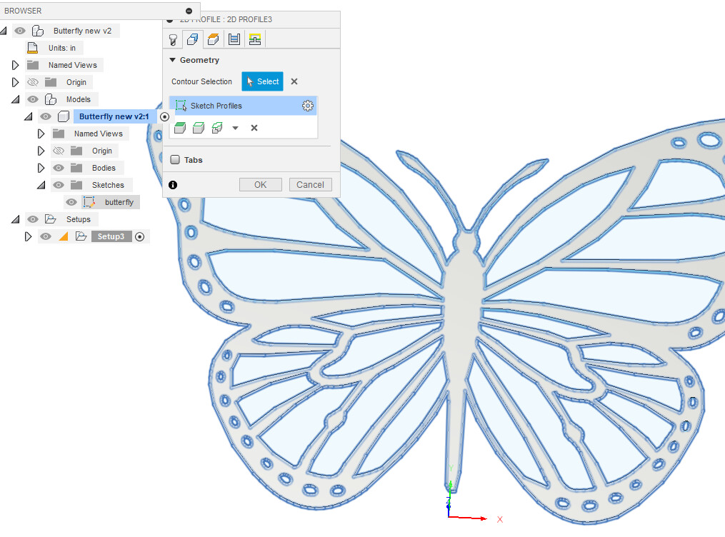
Let’s stick with the “sketch” selection for the remainder of this demonstration.
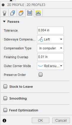
I usually skip the third tab and allow the default values. Moving on the the 4th tab. Here are my choices.
And the fifth tab. Once again, my choices often but not always.

When you hit OK, Fusion 360 will generate the cut path. You can watch the simulation to make sure it is cutting everything. In this case, it is giving me an orange warning sign to say that it had to skip a contour. It must be an awful small contour because not only do I not see it…but I don’t miss it. So I move on with life and the project.
Now you click on “Post Process” in the top menu bar and it brings up this next menu. This step will create the g-code for FireControl so save the file where you can find it later. You will have some serious choices to make in this menu because if they are wrong, you item will not cut out correctly by the CNC plasma cutting system (no matter what table you are using).
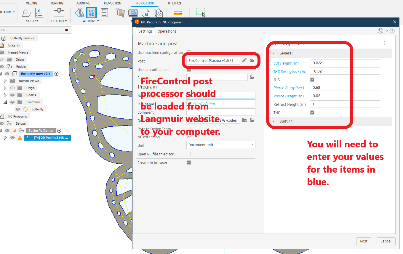
Edit: If you don’t know what your values should be for (suggested values):
Cut height: 0.060 (inches)
IHS Springback: 0.020 (inches)
Pierce Delay: 0.50 (If Hypertherm, you will probably need to increase - see if you get an error)
Pierce Height: 250% of your cut height. So if you are using 0.060 for cut height, then Pierce height should be about 0.15 (inches)
Easy peasy, lemon squeezy. Right?!