So I have a cut program that is pretty much curves, with a 2" hole in one portion of it, that is going to be drilled since it has to be precision for a pin.
How would I get a solid x,y location to pre drill the hole, then put the plate on the table to cut the outline?
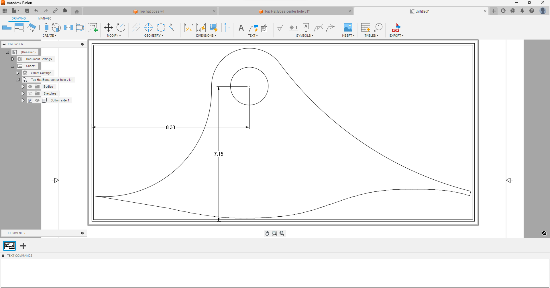
Given that my stock will have a good 90* corner to reference off of. Top hat boss v4.f3d (487.2 KB)
If your design includes the hole, then you can use its center location for a ‘center punch’ operation which will provide an accurate mark to drill. This is trivial if you use SheetCam for your CAM tool (you use a ‘Drill operation’ and SheetCam will automatically ‘punch’ the center of the hole, no matter what the diameter is. It requires some extra work if you use Fusion for CAM and I’ll leave it to others who are familiar with Fusion to explain.
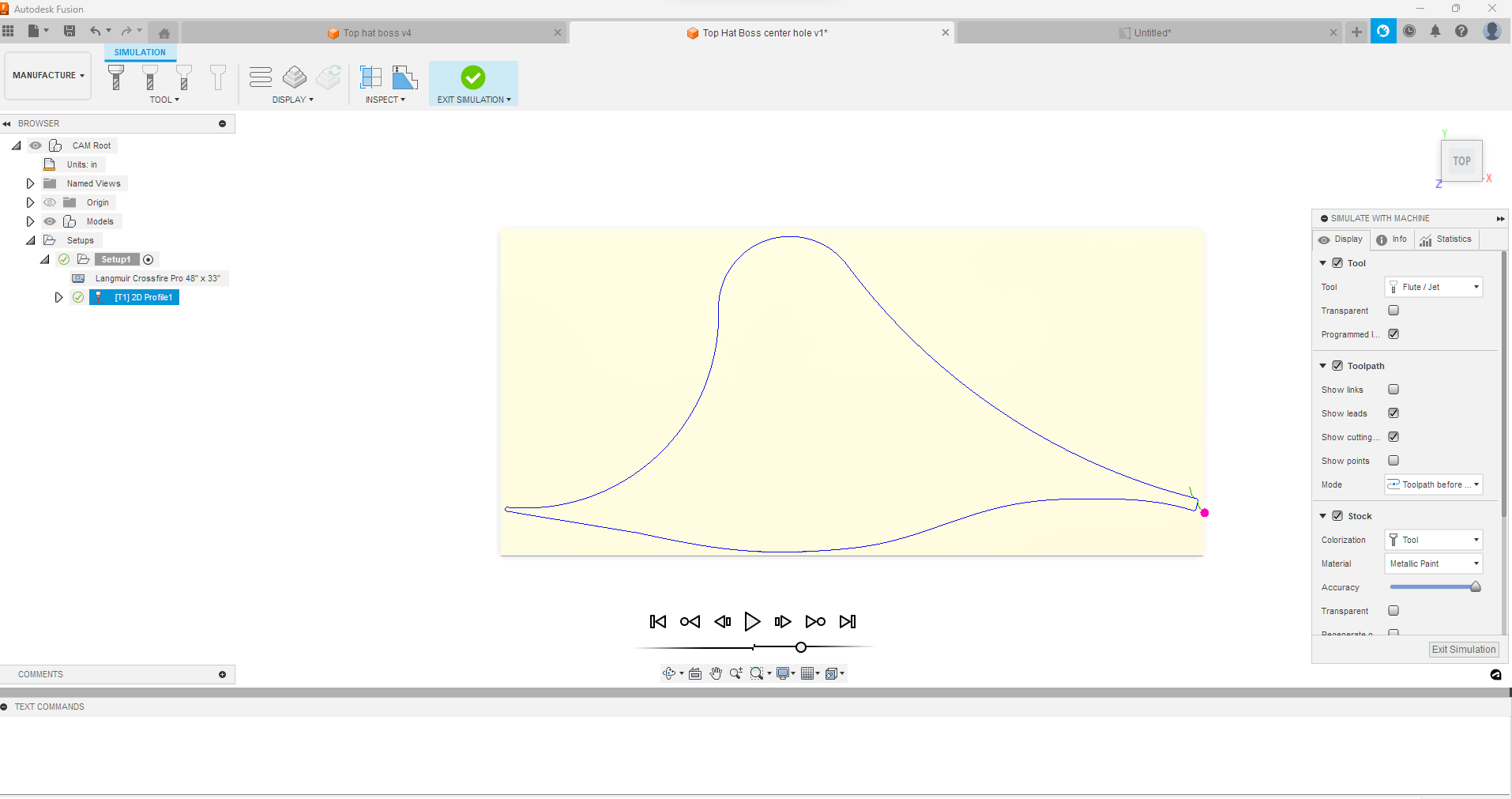
I worked out a toolpath that legitimately will pierce very close to center: Make the hole 0.001 inches larger than your kerf width and set it to No lead-in/lead-out and no pierce clearance. From what I remember, when I tried this, Fusion discarded the hole if it was exactly the same as the kerf width. I just tried it again. I believe it works. I made a hole that was 0.046 inches and my kerf was 0.045 inches and it gives me the indication that it did not discard any of the contours. You can’t really see any action with the simulation.
To line up your plate, cut the outline from a scrap piece of metal. Keep the skeleton of the scrap clamped to the table. Then you can easily line up your piece of metal to be cut.
This hole has to be nuts on. 2" bore that is a .001 slip fit for a 2" pin going through - this 1" plate, a cylinder rod end 2.5" then through a matching 1" plate underneath (that I also have to cut). The curves on the outer body of these plates mate up to the frame it is being welded to.
This is why I would like to be able to find the x.y based on a rectangle piece of stock so I can bore it on the mill, then plop it on the crossfire and finish it off.
One thought is to do as @ChelanJim suggested and have the center point, but don’t cut it, see where the torch drives to from 0,0, note it, then pull the stock, mill it, then back to the table to cut the contour. I just don’t know how accurate that will be as compared to the original F360 design.
The stock will be referenced by a fixture on the crossfire to keep a constant 0x,0y corner.
I guess so. Recently finished and pass an exam I’ve been studying for so a have a little more free time on my hands. I’ll be around a little more often again.
Permanent marker setup is really nice to have for bend lines and this type of marking. For your hole situation I like mag drill but mill would be samething.
I believe @holla2040 said it’s a new year and the toy fund for buying stuff starts over.
If you like the idea of marking center of hole with plasma cutter. You can also do small cross in center of circle and do open lines with center compensation as the guys said above. GL
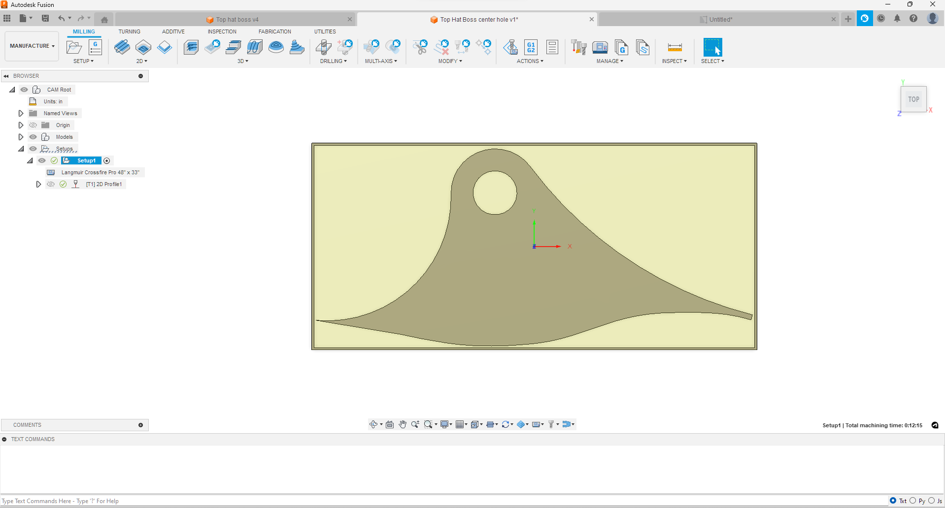
Copied and pasted one of them to a new item, drew a rectangle around it with a border to extrude for later reference, dimensioned in a drawing, then under mfg, reduced the stock to leave to 0,0", and box point to my designated X0, Y0 point, and only did a contour of the outer body.
@davebogdanski had a bunch of trial and error with spring to get it just right I bet. Let me know if you any help setting it up and using it. I might do a Daniel defense sign with wood backer and this is how I design and mark the holes in wood.
Seems like a lot of work when all you need is a short blast from your torch at the center point. I use height between pierce height and cut height with an on time of about 100mS.
What is the dia of the blast marks, and are they centered?
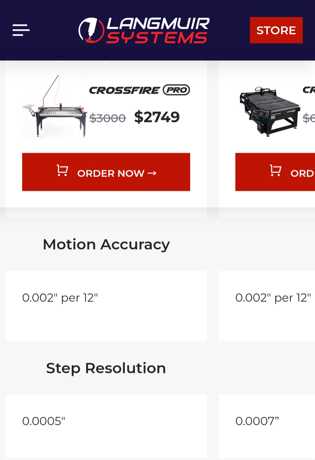
I think time wise they are about the same. I need to practice on the whole pecking holes a bit more. All of my attempts have not gone well in the past, including the 1.70 post processor. It would be interesting to see how accurate the two methods are - based on the +/- .001 of the table.
I do projects similar to this every day at work. I think you are over thinking the accuracy of a center point.
What we do on our parts we have a the company that does our burnouts put a hole about a 1/2 inch smaller than desired size. Then we set the parts up and machine to the desired size where it needs to be.
I didn’t measure the diameter as it’s a swallow well, akin to literally a center punch. EXACTLY centered (at least as much as you can get with a Plasma Torch. The PP uses the center of the hole as the goto coordinate.
EDIT: I’ll also add that the peck is very consistent so if it has any offset, all drill marks with be fairly accurate with respect to each other.