I can’t seem to find it anywhere. When I import a dfx file. If I want the part to be bigger how to I expand it.
1 Like
Select all of the part and then use the Scale command off the sketch drop-down.
I am still struggling with this as well.
I thought that is what I was trying to do. I have a new laptop on the way tomorrow. Going to start over. I think the one I am using is not up to par. Do you know of any videos to watch for this problem or just keep watching the langmuir ones?
Here’s some more detail in case that helps. If not, I’ll try to do a screen record of doing this tonight. These are Windows based directions so if you’re on a Mac they’re likely pretty close to the same but I can’t confirm that
First, there are 2 types of scaling - the sketch or components. Unfortunately they work slightly differently and F360 doesn’t really make it clear when you’re not doing it right for what you’re trying to do. I’m going to outline how to scale a whole DXF you’ve brought in that you got off the web or somewhere.
First start a new project. Make sure your units are set to the correct ones you’re using (I do inches).
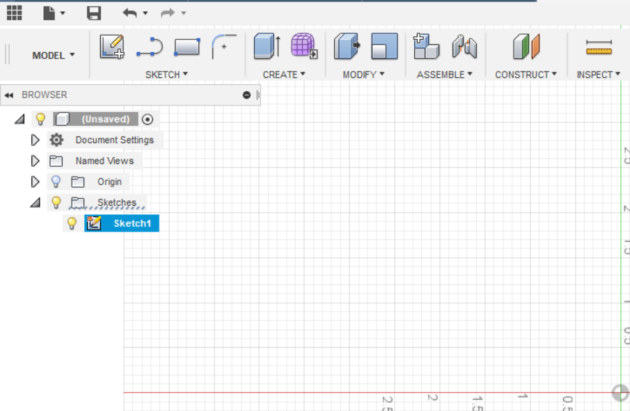
Create a new sketch using the menubar icon for a new sketch.
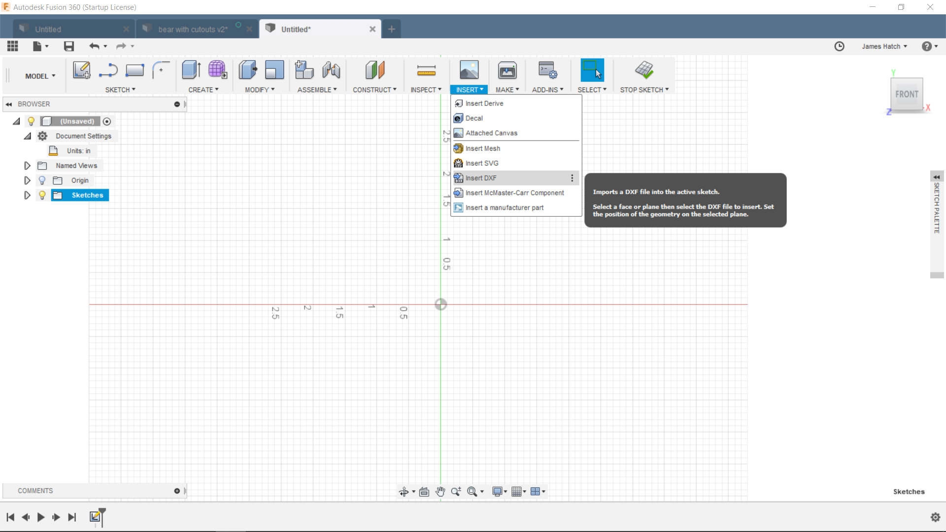
Click on the Insert menubar icon on the upper right of the screen and select DXF.
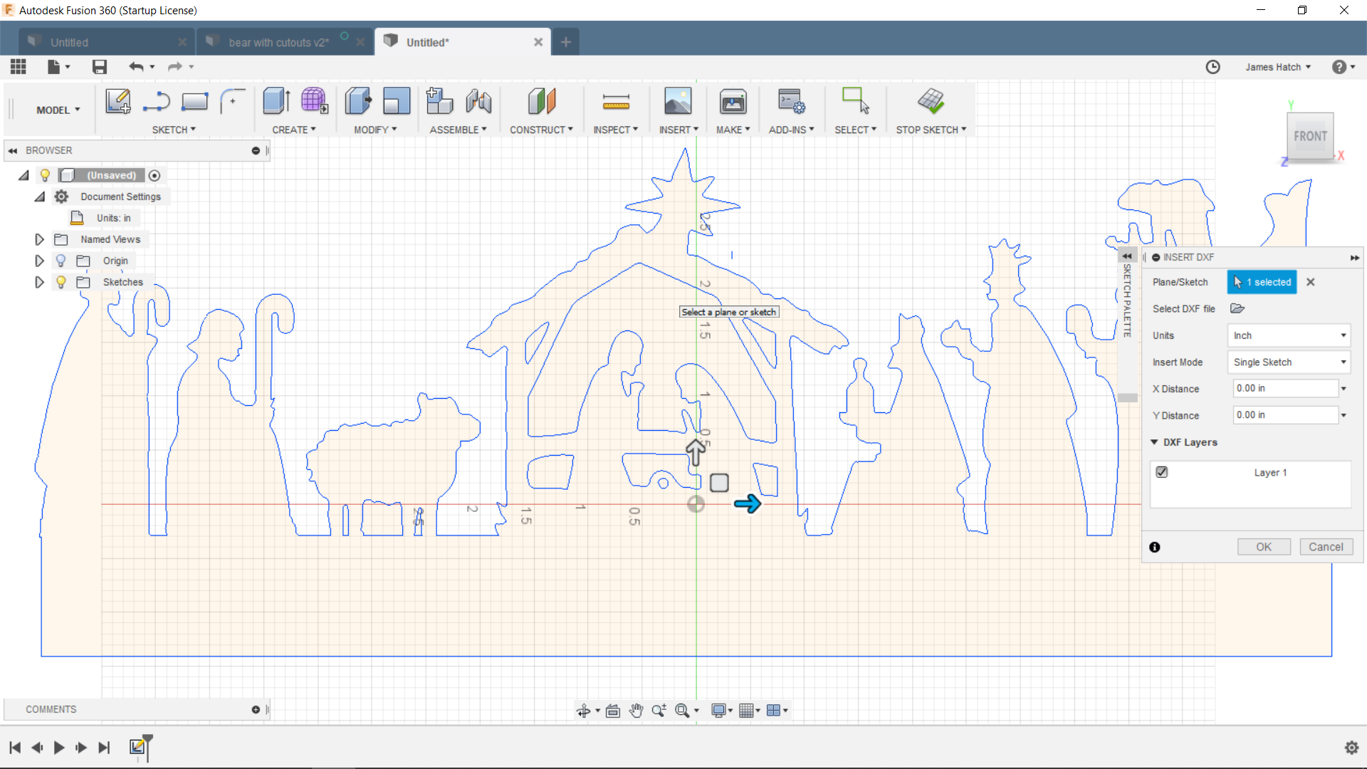
You’ll get a pop-up where you can select the file. Click on the little file folder and you’ll get a standard file search box. Find your file and click ok. You’ll see it says 1 file selected. Click ok in the pop-up.
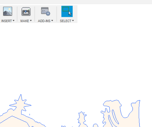
Now your DXF is on your workspace canvas. Probably not the size you want or you wouldn’t be following along ![]()
You can tell the size by zooming in or out as needed to see the whole thing against the rulers (a mouse with a scrollwheel makes this really easy but touchpads also work well vs the magnifying glass icon & control).
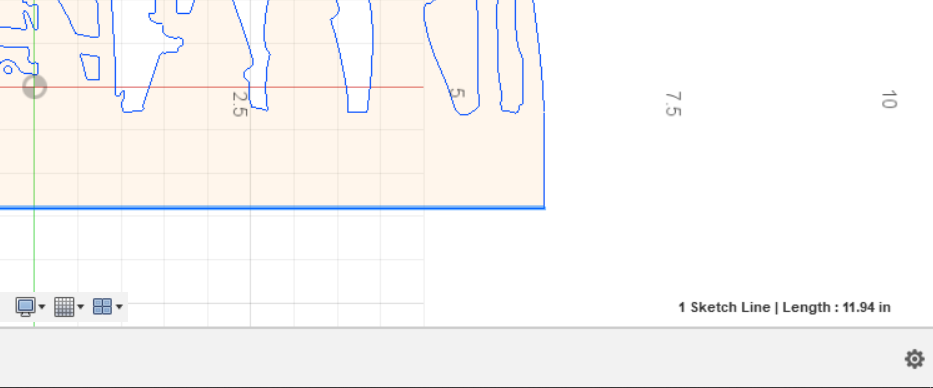
I like more precision than I can get just looking at the rulers so I either click on a long line segment in the design or I’ll draw a box around it to see what it says the dimensions are. Then I decide what I want them to be and use the PC’s calculator to figure out the scaling factor - for example, if it’s 12" wide and I want to make it 18" wide I divide 18 by 12 and come up with 1.5. That’s my scaling factor.
If I drew a box to get the size, I delete it now.
Now here’s where it gets non-intuitive. If the far right icon on the menubar says Stop Sketch, click it. You can’t scale the whole DXF easily when you’re actively sketching.
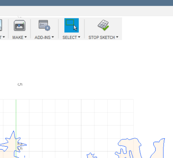
The Stop Sketch icon will disappear.
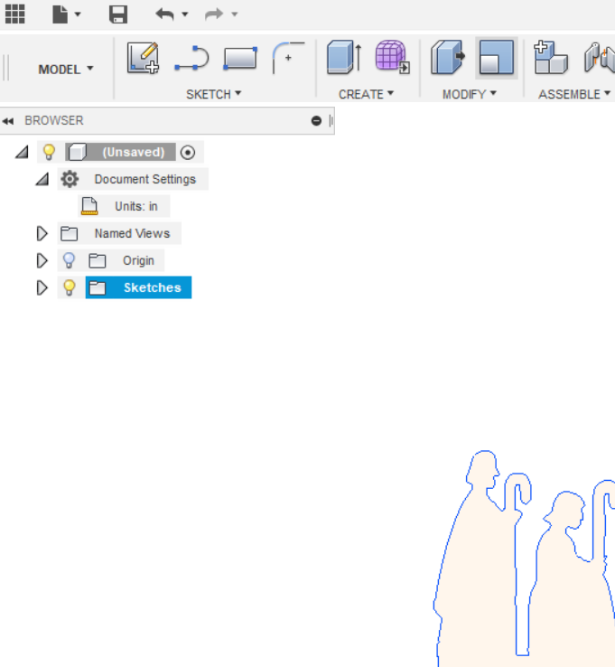
Now make sure the sketch is selected in the project tree in the left - it will be highlighted if it’s selected. If it’s not, select it. If the sketch is not selected you’ll be in component mode when you go to scale and the following won’t work (you won’t get the options you need in the popups).
Now click in the Modify icon in the menubar. Halfway down is “Scale”. Click that (since I do this a lot I added it to my menubar so I can save a click - you do that by clicking the 3 dots on the right side of the Scale line in the Modify menu).
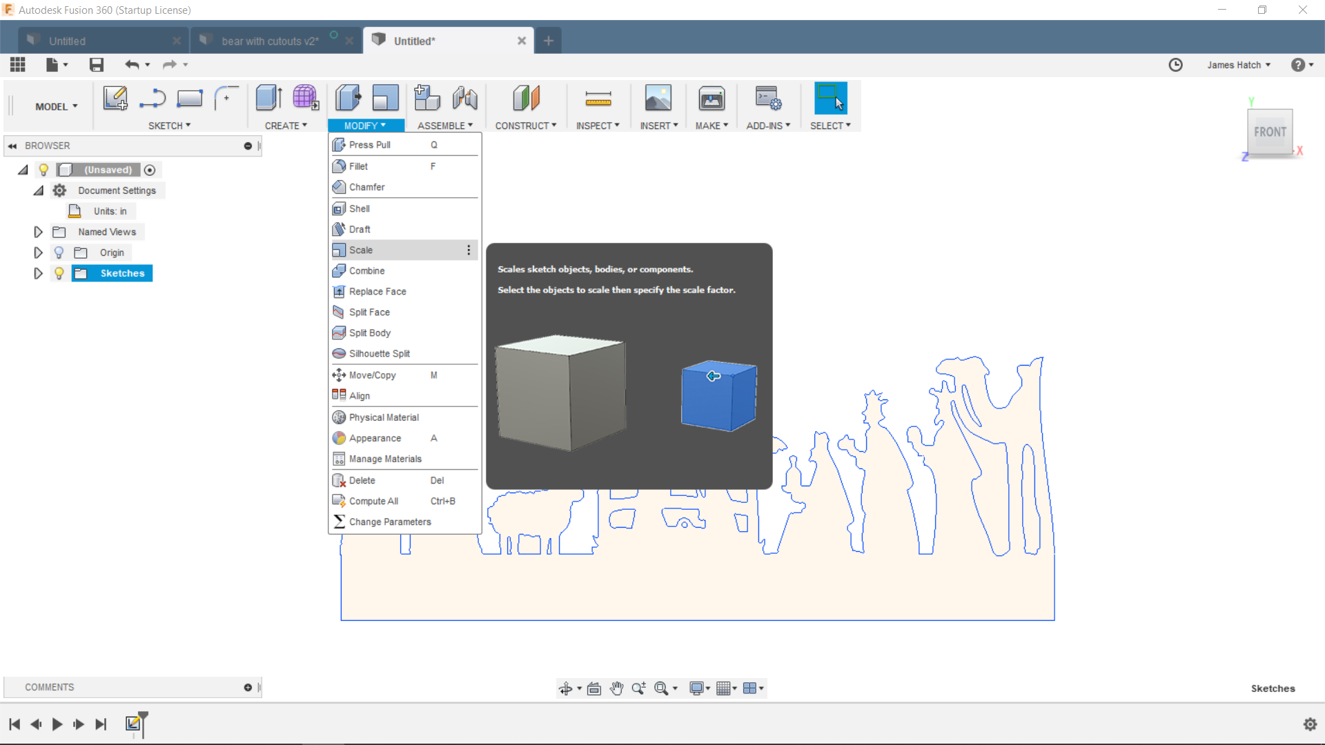
This will bring up a pop-up with 3 fields. If you only see 2 fields it’s in component mode, probably because you’re still in sketch mode and didn’t click the Stop Sketch icon before.
You should see a pop-up with 3 fields that include the sketch (Entities), Point (alternate way of selecting the thing to scale) and the mode (Scale Tyoe).
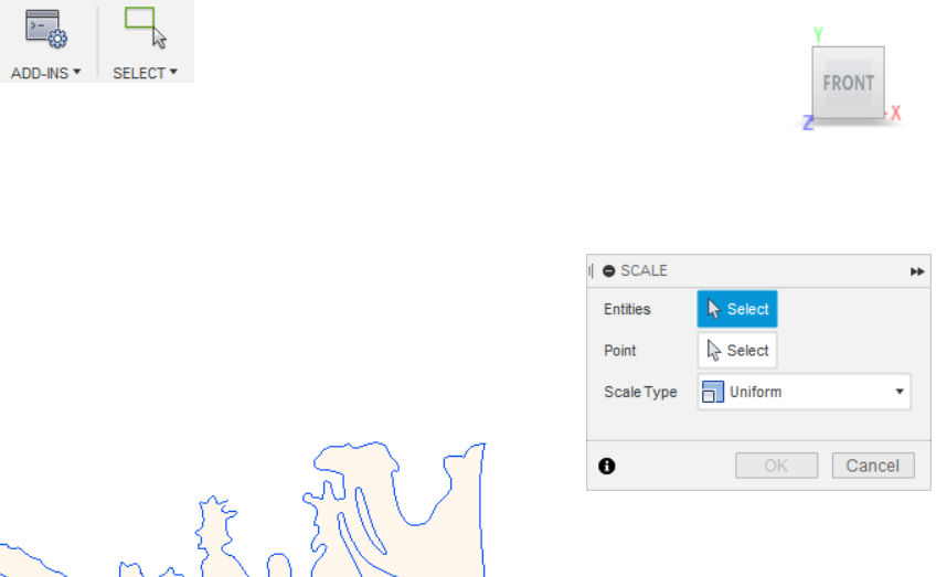
Make sure the Sketches tree entry is expanded and the Sketch (Sketch 1 in this case) is highlighted. When you do that (click on the triangle next to Sketch and then on the Sketch name), the Scale popup will display the Scale Factor field like the pic below.
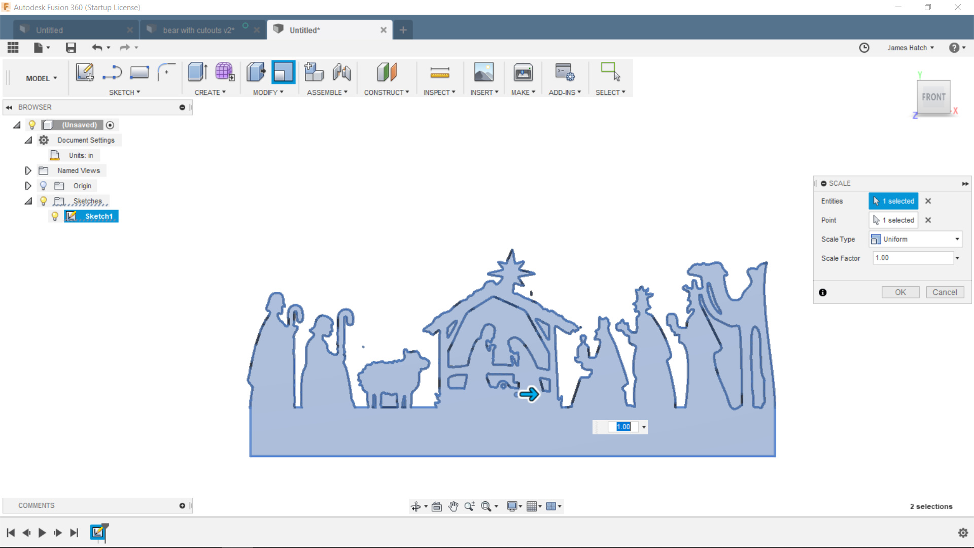
The mode is probably defaulted to Uniform. This means that the X, Y (& Z if you’ve made it 3-dimensional) will all scale by the same percentage. That’s what I usually do. However, if you click the drop-down you can select an option that allows you to scale each dimension differently if that’s what you want - the pop-up will expand to add fields for how much to scale in the X, Y and Z directions.
I leave it at uniform and I enter the scale factor I calculated above. So in my example I’d enter 1.5 and click ok. The DXF will resize. (If you want it smaller use a negative scale - 1/2 size would be -.5)
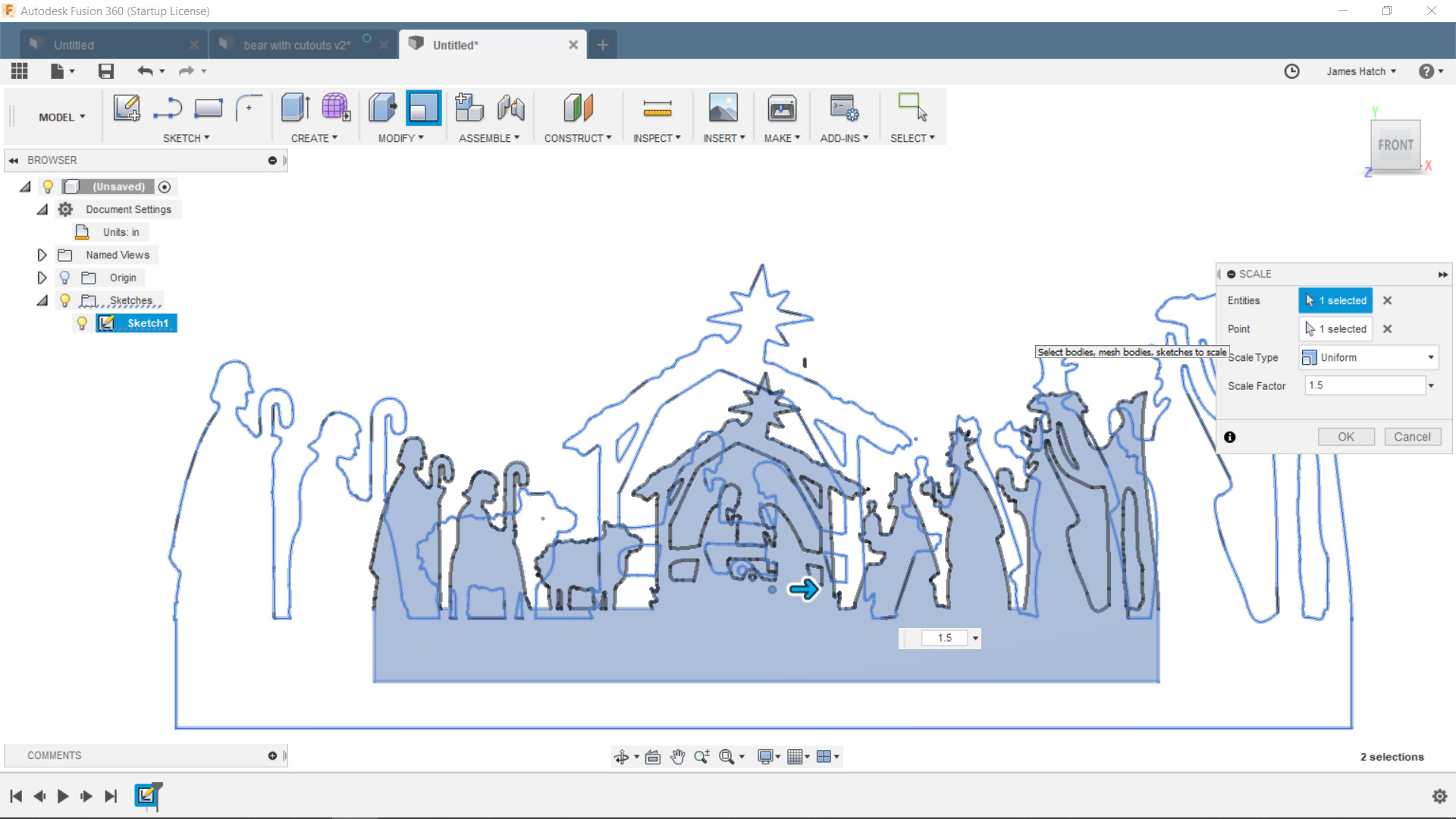
The outline of the new size will display. Click Ok and it will resize the design for you.
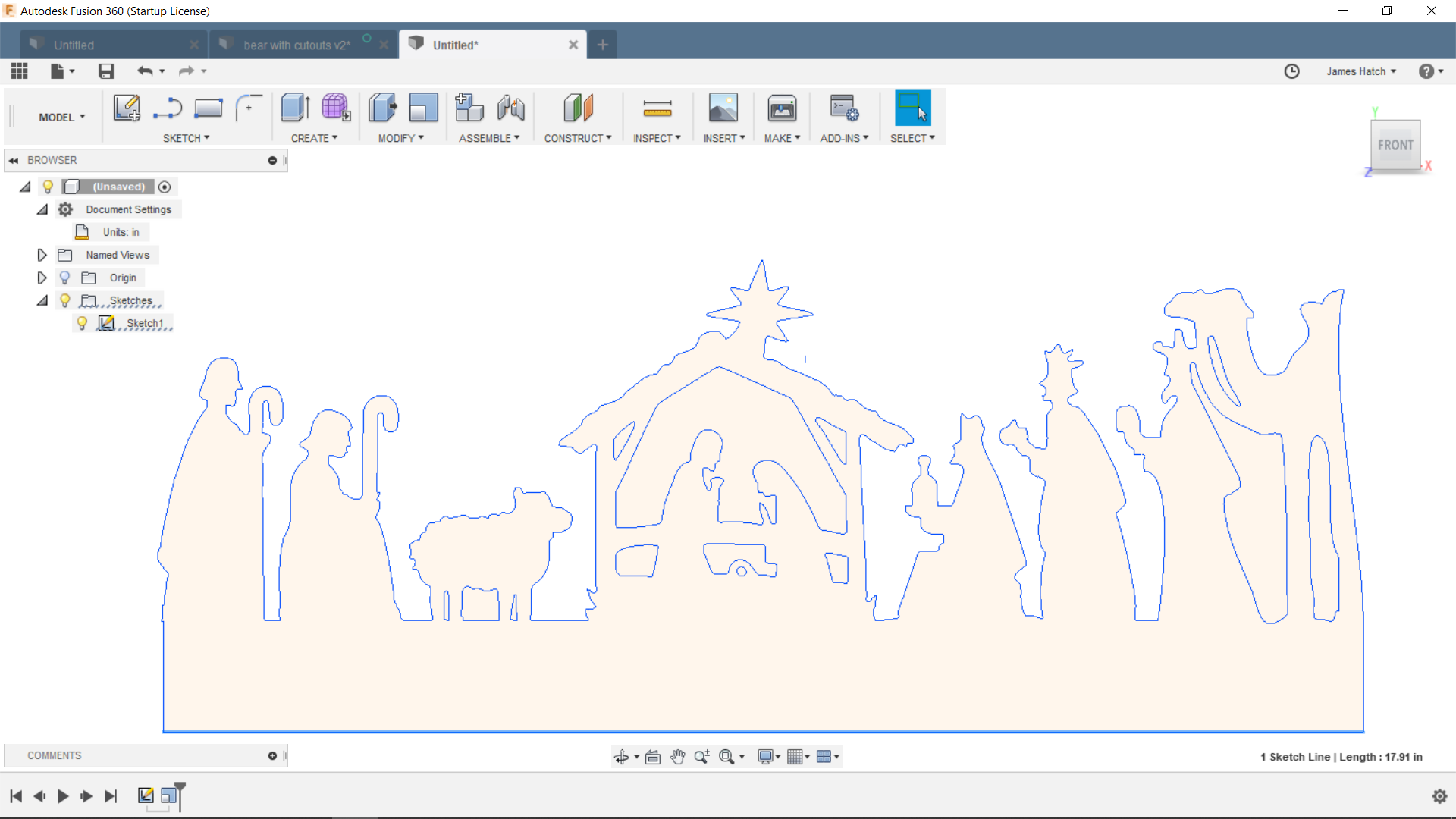
Notice the lower right corner displays the new size of the bottom line that I’ve clicked. It’s now 17.91 (vs. the 11.94 I started with above).
Now you can define your tool path and all that good stuff you really want to do ![]()
Let me know if that helps.
(BTW, why I can’t just do a normal Windows object handle drag to resize I don’t know. Well, actually it’s because it’s a CAD package nit a drawing package and typically CAD needs specific measurements for things. Still it’s hard not to just select all and want drag handles ![]() )
)
9 Likes
James, thank for for you patience and Guidance for us guys that are comepletely new to this. I will be working in my computer tonight when I get home from work and will be following your direction. Again, Thank You.
1 Like
No sweat. I’m a computer guy so I’m a bit more comfortable with this than a lot of us might be. I teach CNC machine operations at our local Makerspace (lasers, routers) and the software design side is the same - just the operating software (Mach 3, Shopbot, LaserCut) that’s different.
One of the non-intuitive parts of F360 is if I select the design while in sketch mode I can do a Modify|Scale and I get a pop-up that has the select & scale fields and it looks like I should just be able to enter my scale and it would resize. But it doesn’t. And it doesn’t really tell you it didn’t do anything. It can be frustrating when you’re trying to figure it out. At least give me an error 
1 Like
this is what i was struggling
i wasn’t selecting edit sketch
I’ve updated my post above with pictures to show what you should see if you’re following along.
This is a great explanation… I had to figure it out by watching videos and not having all the information. I received a .dxf from a friend of a project that requires many tool paths. When I finally resized it and figured out how to adjust my settings to be able to cut the details, I was able to create all of the tool paths with the appropriate inside/outside leads in the cuts.
When I posted the file and created the .tab, I loaded the G code into Mach 3 and there’s just a bunch of circles and crazy lines of code.
There was one warning: Warning: One or more passes were discarded due to linking constraints.
Generation completed with 1 warning(s) in 4.7s.
However, when I run the simulation it shows all the tool paths properly… This is getting very frustrating but I am not giving up. I do question if this is all worth the countless hours of mistakes and rework though!
This is why everyone doesn’t make steel projects ![]()
It’s like anything else that requires skill - it’s gonna take time & learning. Without a doubt it’s easier to get super high quality results without anything resembling the training & effort that it takes to be able to produce those results manually.
I think we often forget that the alternative would take 10,000 hours of practice. It’s easy to get sone cool stuff you couldn’t conceive of before but then just focus on the parts you struggle with. I know I couldn’t remotely get close by hand - I’m not that patient or sufficiently hand-eye coordinated ![]()
1 Like
Jamesdhatch, can you tell us why some cut paths were lost due to constraints ?
Also thank you for your time and help , being an ole tired welder/part time dirt farmer I think I speak for all of us that your knowledge has made working with this better .
1 Like
That’s usually because the lead-in/lead-outs is conflicting with the kerf you’ve defined for the tool. Small holes or tight cutouts where the lead values - length, radius and angle cause the head to “bump into” the line so it won’t cut.
Couple of solutions - change the lead in angle to something more vertical (90 degree) if it looks like you don’t have room to slide it in at an angle - or vice versa if you’ve got a narrow shape and not enough room for the lead in or out. You can remove the lead out in case there’s no room for both. You can also define another tool that is narrower or a smaller kerf and use that for the parts that it skipped - your cutouts won’t be as precise as you designed because the kerf compensation won’t be calculated exactly right so the cuts will be closer to the line & so they’ll overlap the line instead of being next to the line by a kerf’s width. That usually isn’t a problem for art pieces though.
James,
Great tutorial do you have any idea why fusion wont let me down size the dxf?
I did as you said and tried to type in - for negative but it stays red and wont work.
Sorry. Try just .5 to make it half sized.
1 Like
worked perfect thanks
Thank you sir. I had been struggling with scaling with neither results nor any error messages. You saved my sanity!!. Lol
When I follow the instructions exactly, I get the drop down for “Uniform” but there is no other option besides “Uniform”. I have the free hobbyist version. Any insight why I can only select “Uniform” on the scale type?
THANK YOU! I need a tutor and this was great
1 Like
Just bear in mind that those instructions were for a version of Fusion that was probably 150 updates ago! Given that there seems to be an update every day or so… ![]()
1 Like