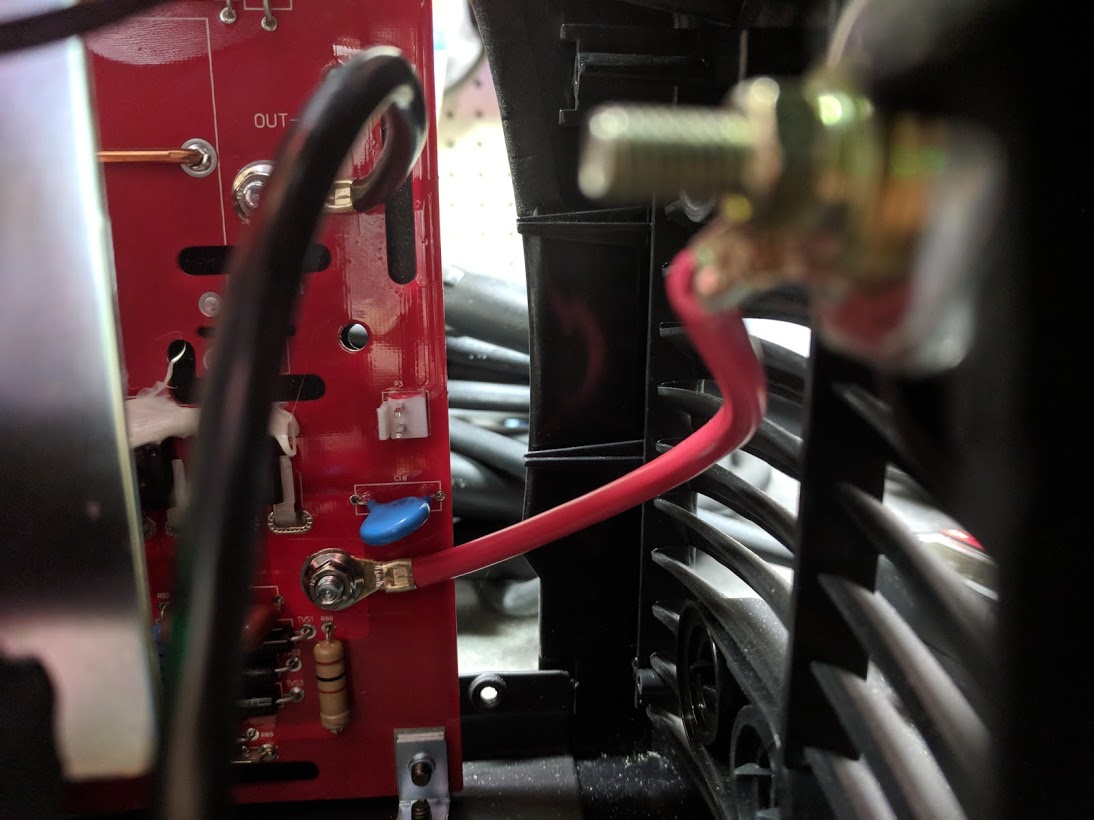
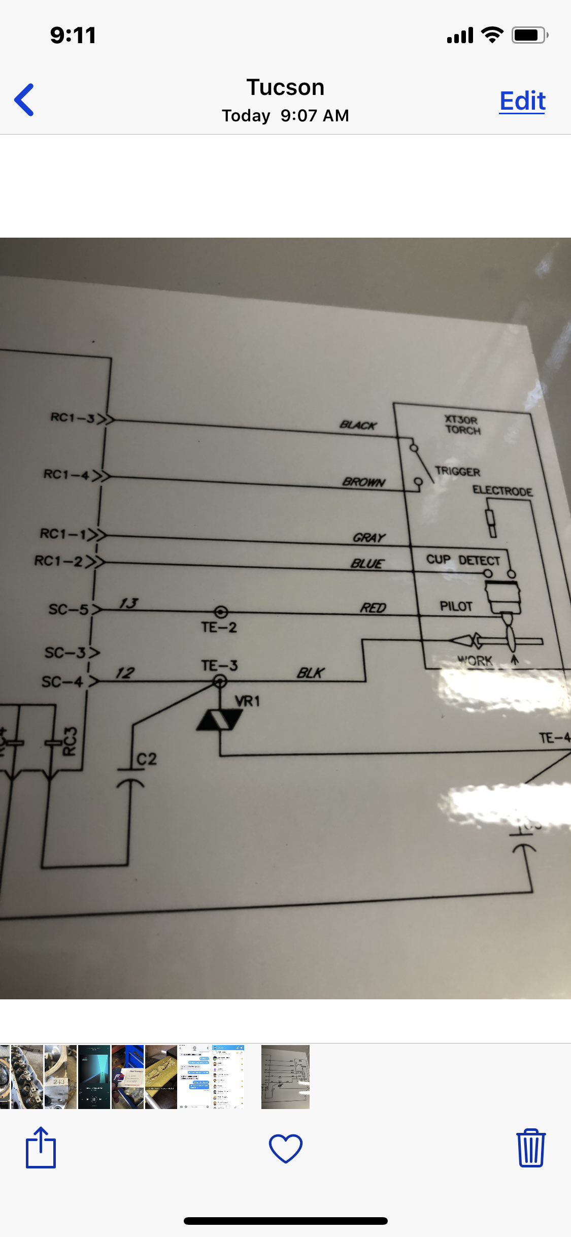
(edited as original wiring picture was incorrect. The test procedures in the CrossFire manual are not the same for the Hobart systems. On the 500i the trigger circuit is Open in a normal state and Closed when activated. The signal is carried on a brown and white wires)
Nothing fancy here, just something other folks may want to consider if they are using a torch without an existing accessory port.
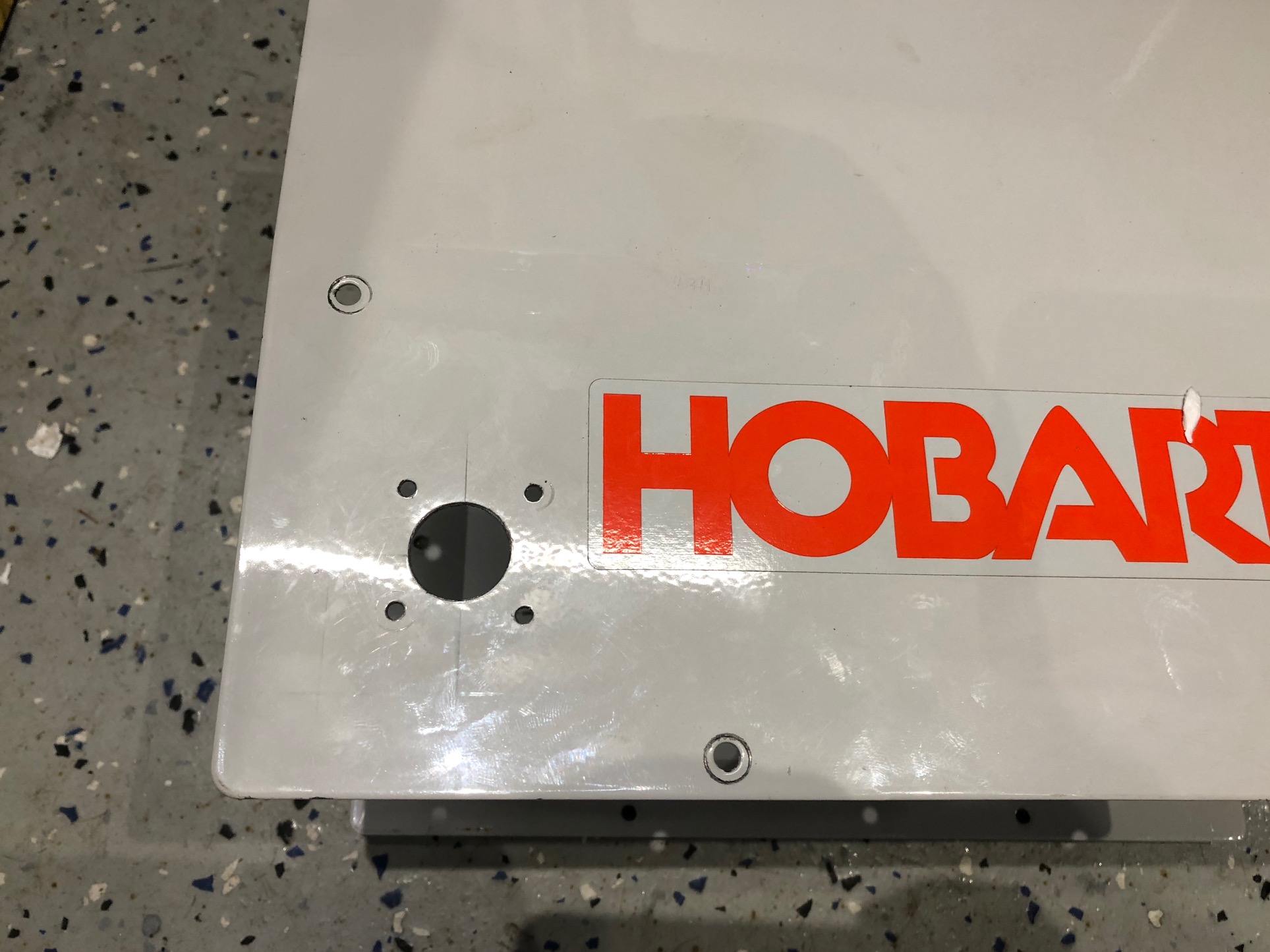
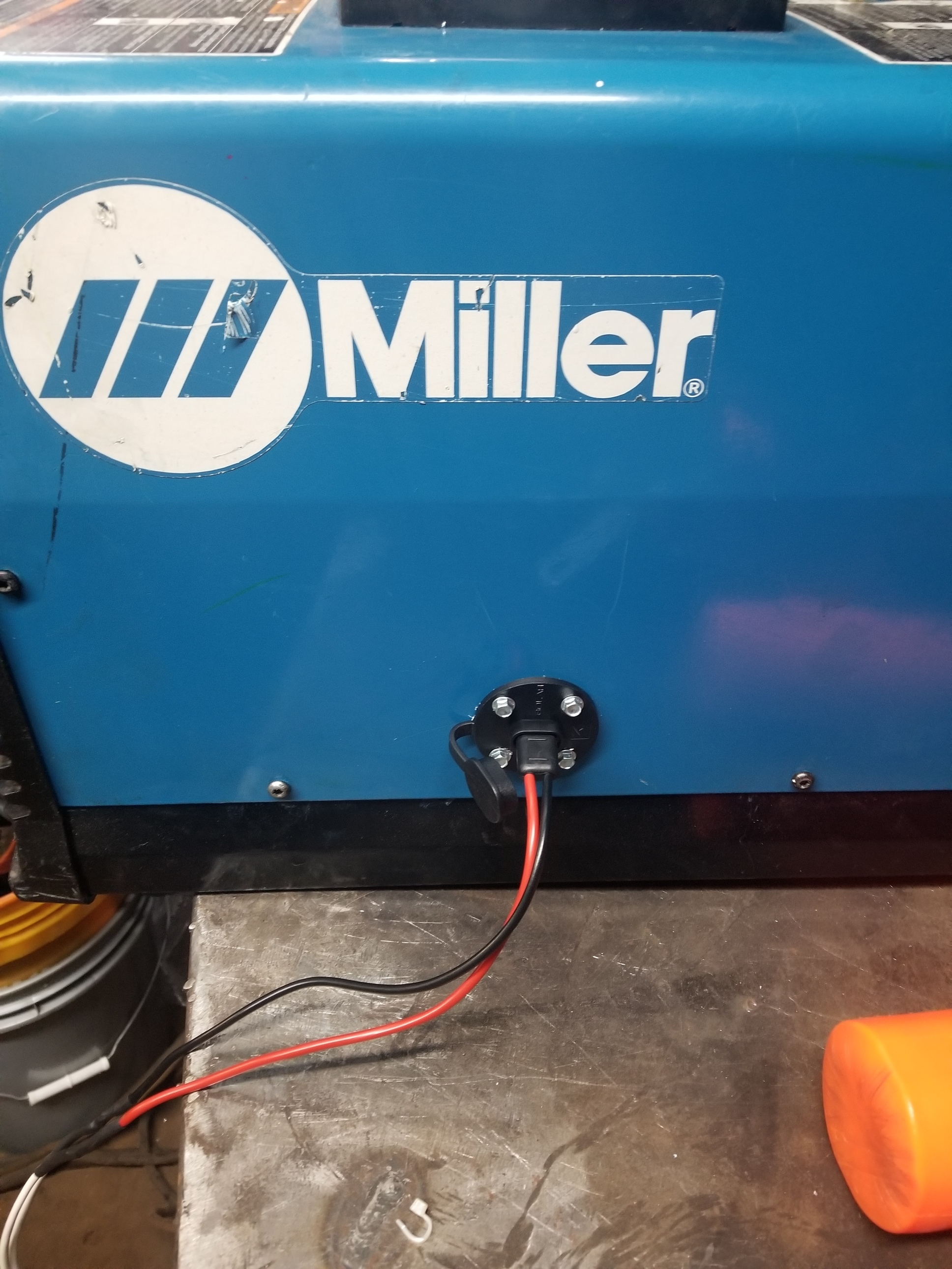
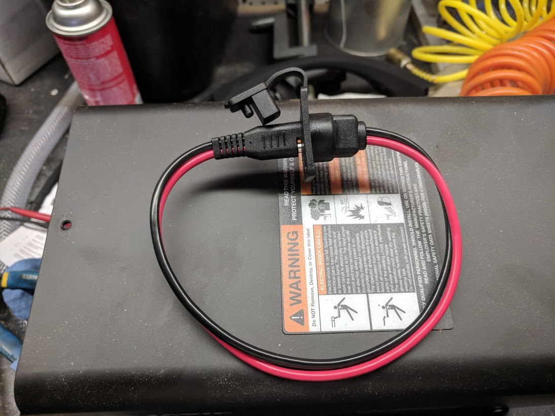
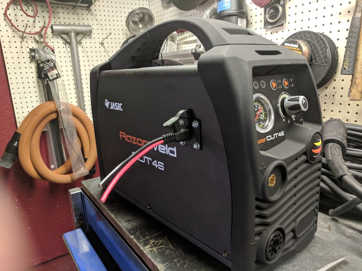
I didn’t want to leave a wire hanging off my Hobart 500i (aka 27i) so I installed a simple 2 pole covered connector to the cover.
The port I used is a simple 2 pole waterproof flange plug used for connecting solar panels to RV roofs and similar applications. They can be found on Amazon for a few bucks.
I drilled the hole for the port on the outer casing to keep the metal away from the circuit board and I figured if I ever decided to remove this plug I could just cover the hole with sticker.
Perfect solution, will do something similar to my 27i soon. Unfortunately, I’m batch 2 so its gonna be a while till I get my hands on my table. I’m glad to see someone else with a Hobart plasma cutter! Let your fellow Hobart owners know how things go using your torch!
Haven’t pulled the cover off of mine yet, is there any room on the back cover for the plug adapter versus the side location?
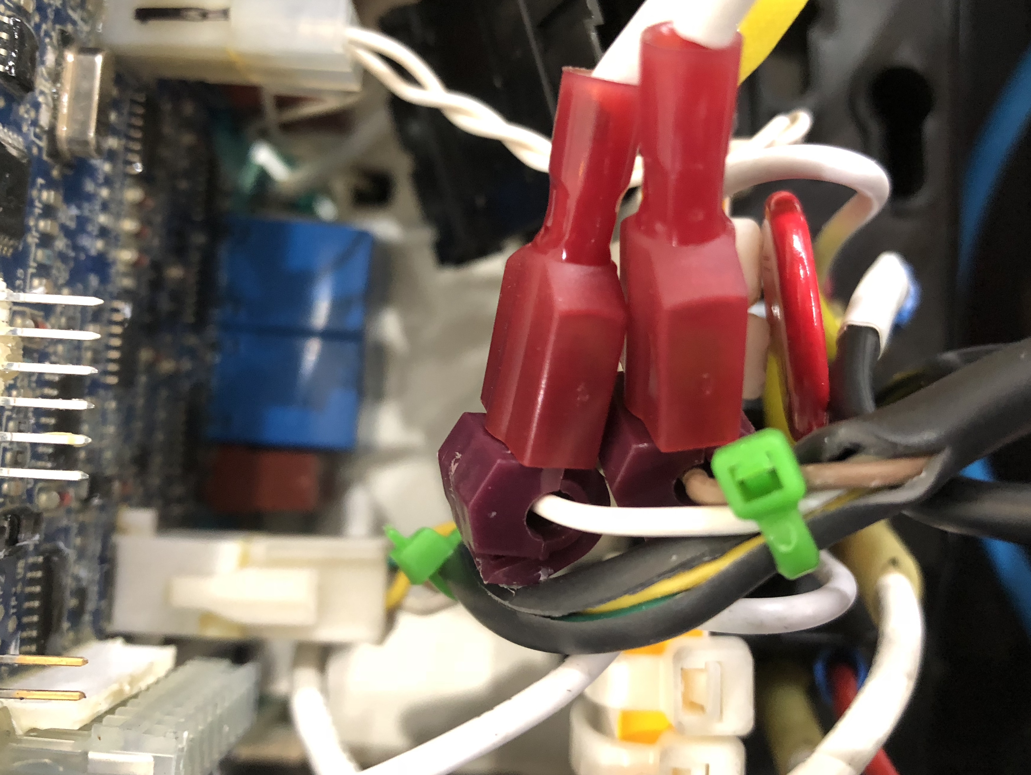
That’s a great idea! I used the provided scotch locks to get up and running until a cleaner idea came along, I think you hit the nail on the head! Great work! And thanks for sharing.
I have a 27i and I having issues Determining which wires to hook it to can you help me with this I was looking at the wiring diagram and I seen the brown but out of the torch it goes to a plug some kind of confused any information be greatly helpful thank you
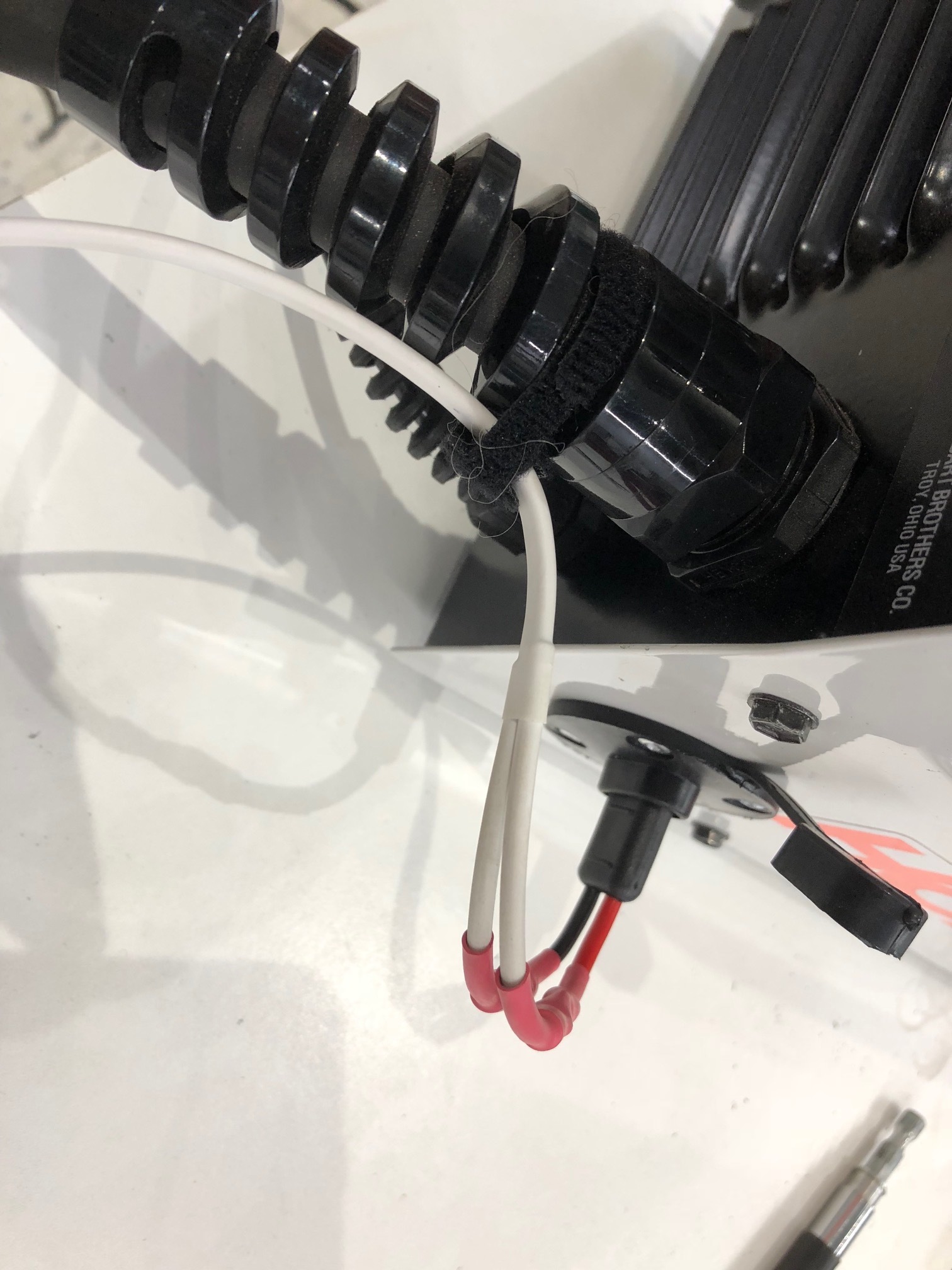
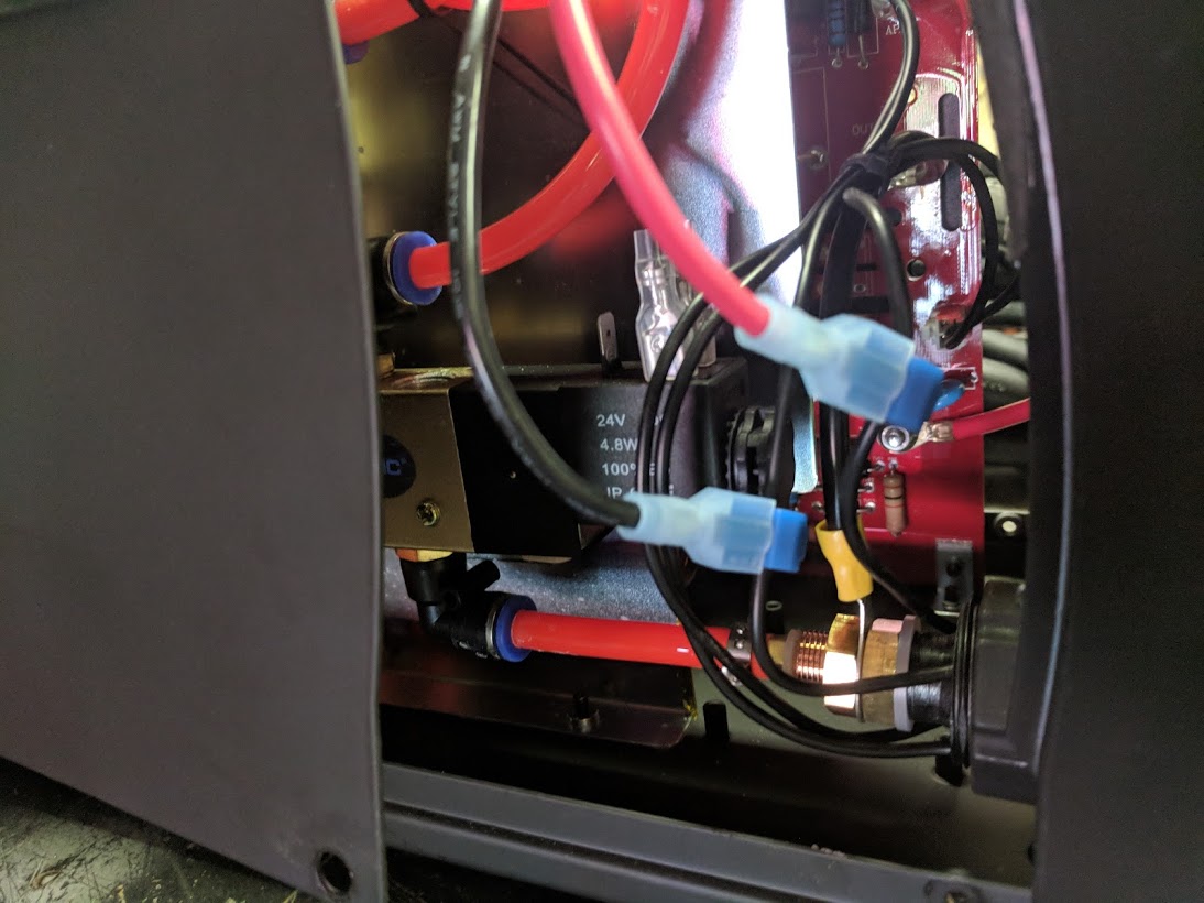
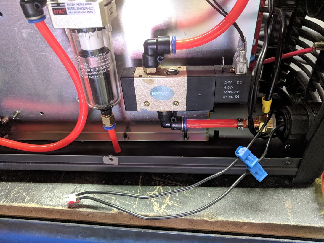
Check the wiring diagram on the inside of the cover for the specific colors to use. There is a bundle of 4 wires from the torch that are together in a black sheath so it may look like a single thick black wire until it gets close to the main circuit board. The 4 wires go into a 4 pin plastic connector that is square (2 rows of 2 wires) and is located towards the front of the board (front of the housing) about half way up from the bottom of the board. 2 of the wires are for detecting the presence of the consumables and 2 are for connecting the circuit on the trigger.
These are the wires you need, you have to cut the black sheath back a bit to get at them. I believe its brown and white but the diagram on the inside of the case is what you need to use to be sure.
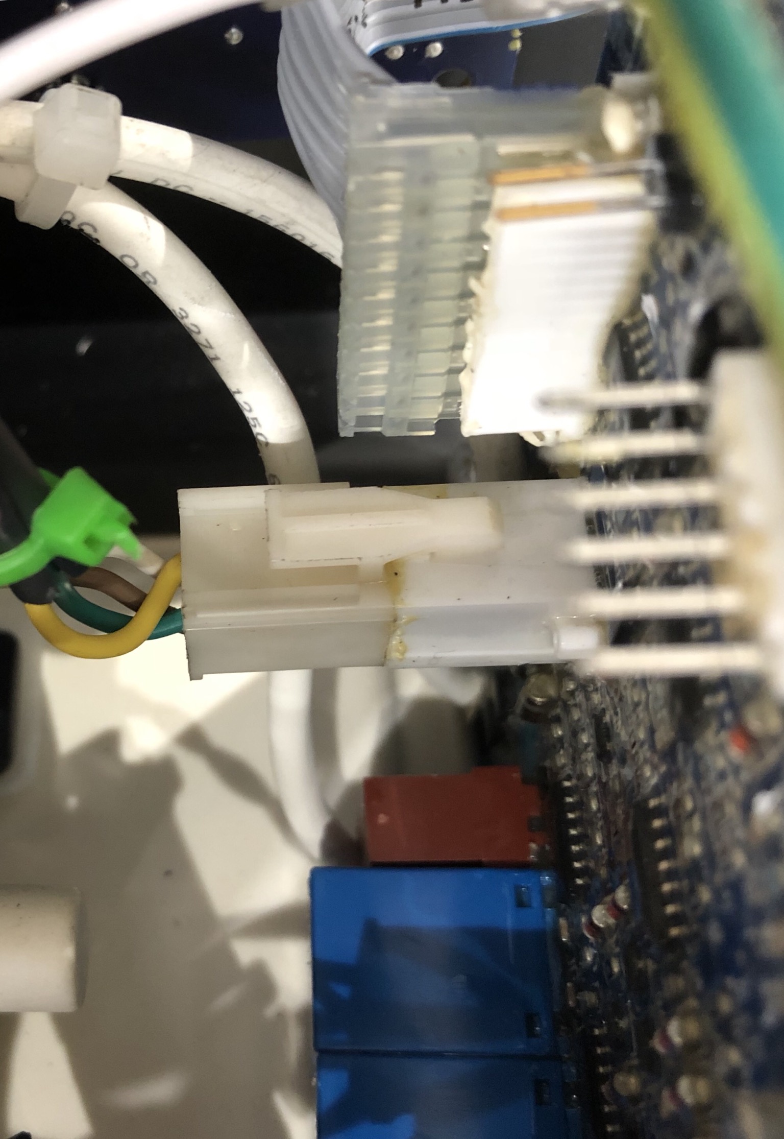
This is the connector, the one with the white, brown,green,yellow wires.
When I plugged mine back in after the splice one of the internal pins was misaligned and not making contact so it seemed like it wasn’t working. It took me a while to figure out that the pin inside the connector just needed to be bent a little.
Do you mean which of the leads on the Langmuire cable to which lead on the cutter? As far as I could tell it didn’t matter on my unit. You are just closing a low voltage signal loop so polarity shouldn’t be an issue.
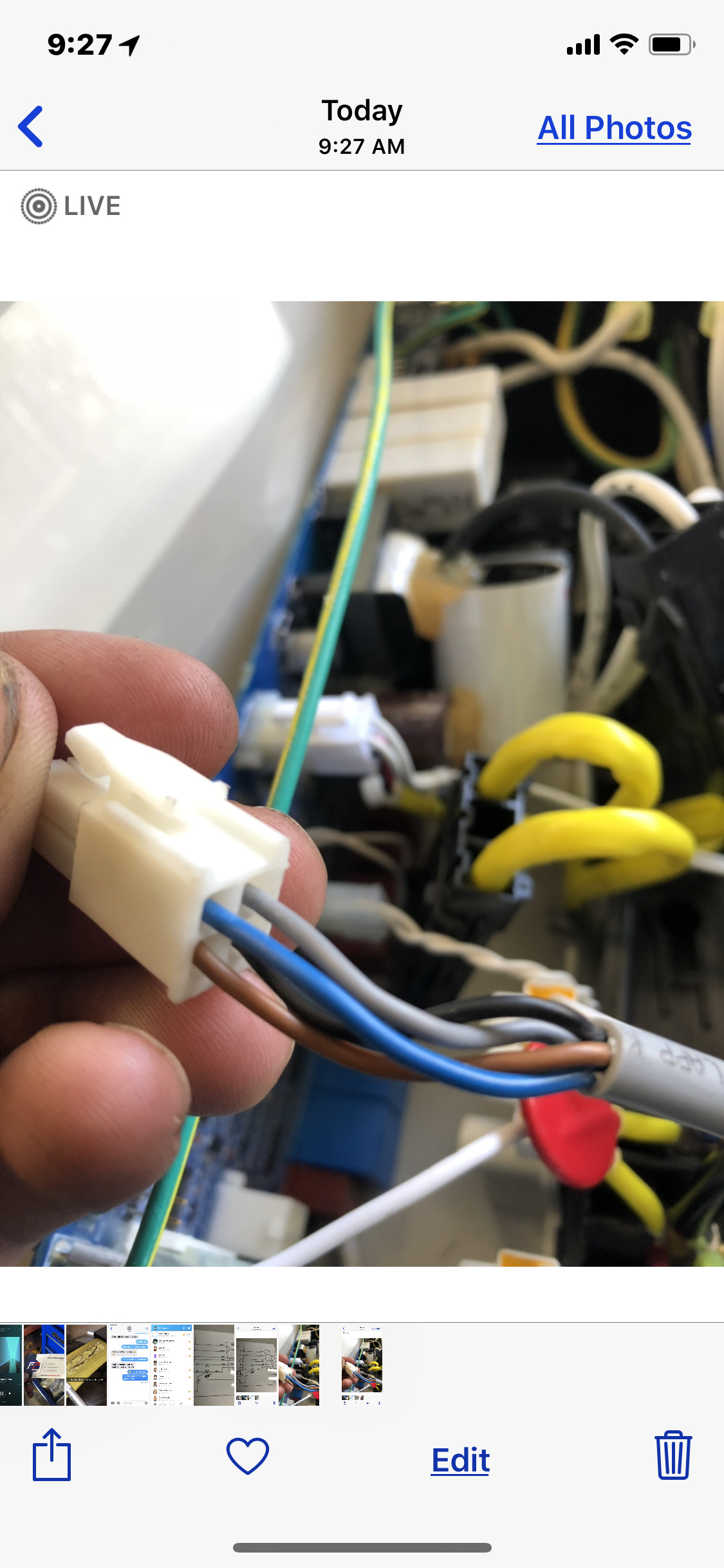
My 27i has same
Plug but has a blue ,grey, brown and black , no white . I had two 27i o hooked it to brown and black first and first time tried to fire made loud pop and plasma wouldn’t turn on again . So dealer exchanged it for me I don’t wanna mess this one up too
Ok so those are ones I hooked
Up on last plasma cutter 27i and it shorted the machine . Just made loud pop and then wouldn’t turn on anymore . Any idea what could have caused that
Did you use the wire colors listed on the schematic?
Those wires shouldn’t carry enough current to cause anything to pop. Even if you twisted them all together the consumables indicator would be green and the torch would fire. There may have been a different issue in your first unit.