Hi,
I just received my XR, which is still in the box. I didn’t order a plasma cutter yet. Budget is not really an issue, and I have 50A 240V outlet. I’m thinking of either the Hypertherm XP 45 or the new 65 or 85 SYNC models. I think the idea of the self contained consumable is cool. Anyone use these?
One question I have is does a 45XP actually cut thin gauge/fine cuts better than a 65 or 85? I like the Idea of having a more powerful machine as I tend to go for overkill (hence getting an XR for my first cmc plasma).
If im not asking the correct questions I’d appreciate any input.
Paul
I have a hypertherm powermax85 and I love it. I am just getting started in this space of manufacturing. AKA it’s new to me i’ve got collectively about 6 months of time on the machine.
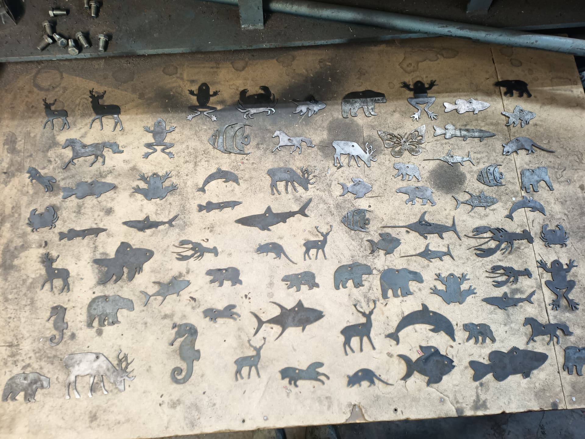
I am ordering all the bits an pieces of the fine cut consumables for cutting intricate signage on metal less the 10g. With the standard tip it’s kerf at .06is blowing holes in the design and not really what I would call quality. I am hopeful that the .03 of the fine cut will be what I am able to make work. Otherwise scale back the details a bit and see how that goes. I will post some output next week.
Here’s the consumables i am running with out the OHMIC Ring.
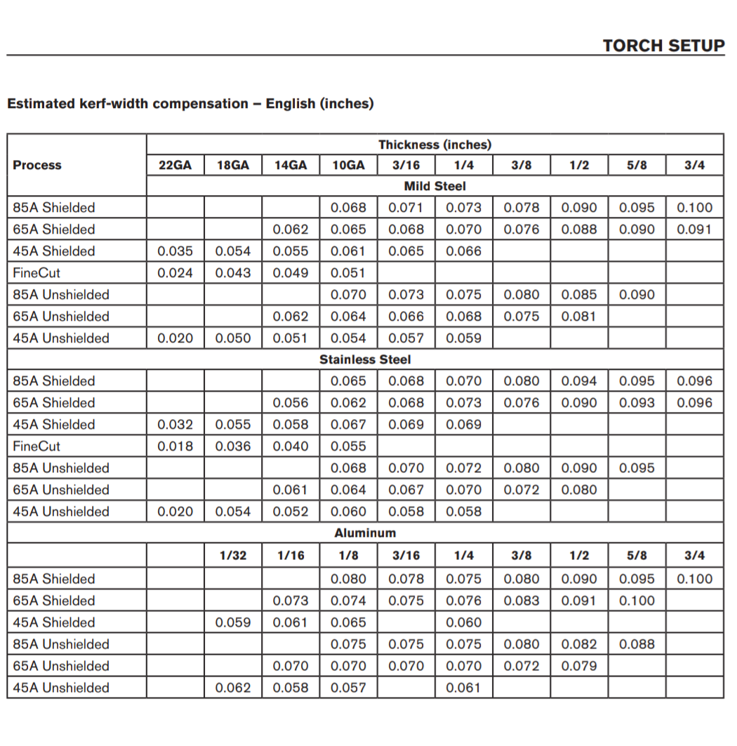
The manual for the PowerMax 85 does include a estimated kerf width chart.
I don’t think you’ll be achieving .03 kerf width unless you’re cutting less than 20 gauge super fast at low amps. Stainless steel also ends up being a smaller kerf width when cut.
I do most of my signs out of 14 gauge where the .003 kerf width savings by going to fine cuts just doesn’t make any sense to me I would rather be cutting at an extra 50 or 70 in per minute faster by using standard 45 amp consumables unshielded and take the penalty.
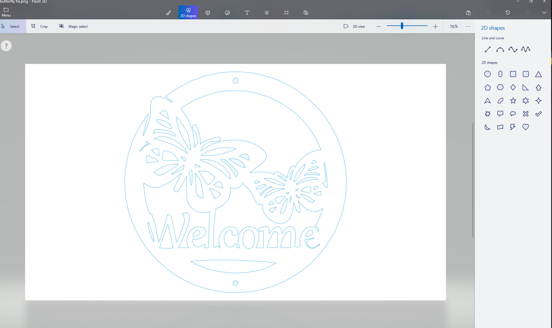
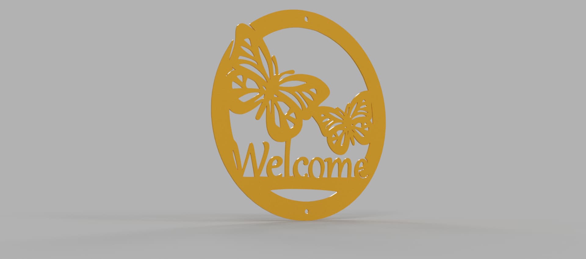
@TinWhisperer, I got to figure out how in fusions to makes these things a single line instead of a bunch of lines for one shape. I think it’s called contours but I can’t seem to figure that out yet.
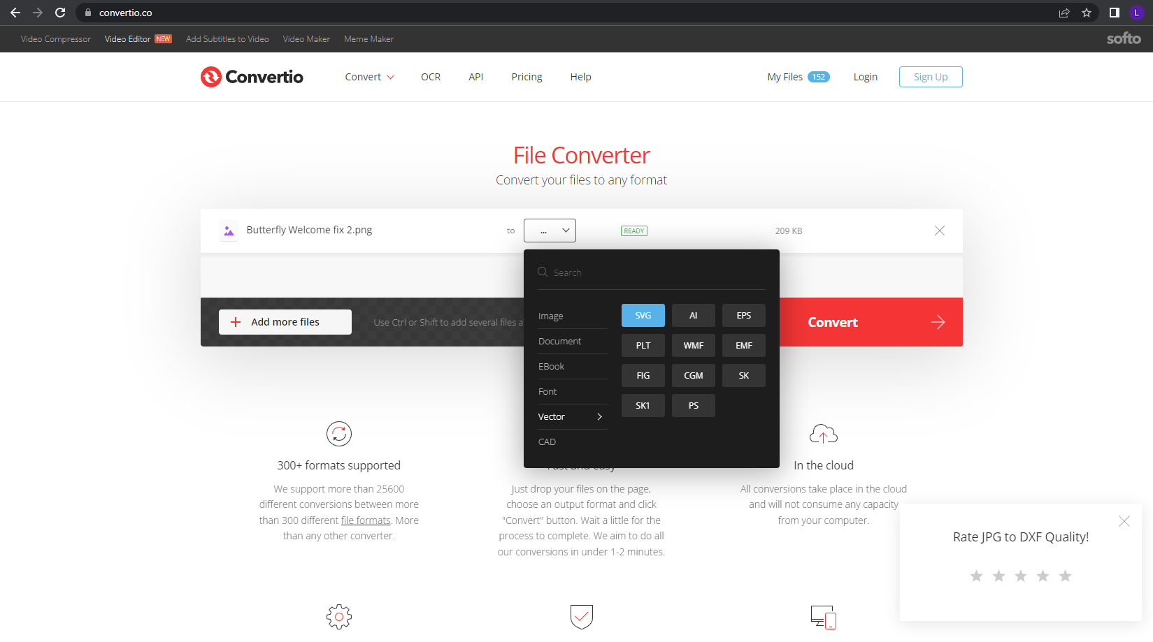
This DXF file when loaded into fusion shows one part of the “e” in welcome having something like 10+ lines, each has to be selected as a contour and that’s just not right… searching for how to close them up. Then I can select the right side of the line for each shape not line.
I still haven’t made it back to a computer today but if you left click and hold on your line it will show you all the layers under it and then you can choose which layer you want from the list.
But from your description it does sound like there’s some cleanup that needs to be done.
In fusion there are open contours and closed contours.
A open contour is just a of collection of lines or arcs that do not complete a closed loop
and
A closed contour is a complete loop that creates a profile within it.
Try double clicking when you’re selecting lines I will select the adjoining lines along the same path as well.
I can check out that file when I get back to a computer.
Thank you mucho for the instructions. I have been trying to figure that out all week. Now to get it going in fusion and set the contours to cut it, let know how it goes.
Nope, not yet. Having a time with the contours not showing up right in the fusion app. When I zoom in they are not on the inside or outside of a line, they are almost always on the outside and clicking them just changes the arrows direction. Not to the inside or outside of a line.