I have this on both X and Y I just push the sheet to that corner (Home Position)
1 Like
Good/Yes.
I realize you are dealing with something much more complicated than just finding one edge.
But while I have your attention, I was suggesting 26 gauge for practice not 16 gauge.
The other thought: How wide are highway road signs??? (Deleted by author: nevermind).
3 Likes
Thinnest sheet my supplier has in HR roll is 16ga
1 Like

Ok I normally never touch this but I must have this time. So reset these to .4 and .2 to match the rest.
Clearance height is where the torch goes to just before it moves to the beginning of the cut path?
Retract height is where the torch goes to when it jumps from one cut to another along the tool path?
What is the difference between this retract height and the one listed in the post?
Top height is the thickness of your sheet?
if this is correct why does fusion not put a value in there?
it knows how thick my sheet is correct?
Thank you as always
@knick That is a good question for the Langmuir guys @langmuir-reilly
This is the documentation from the main site.
"Actual Pierce and Cut Height Values will be set in the Post Processing step below. However, Clearance Height, Retract Height, and Top Height need to be left to the Fusion360 defaults to properly set heights in your G-code program. Be sure to have these values set to the below. "
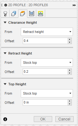
I am not sure but here is my guess, Because Langmuir post processor uses the Fusion 360 defaults as the datum points so every update we do not have to manually reset them.
2 Likes
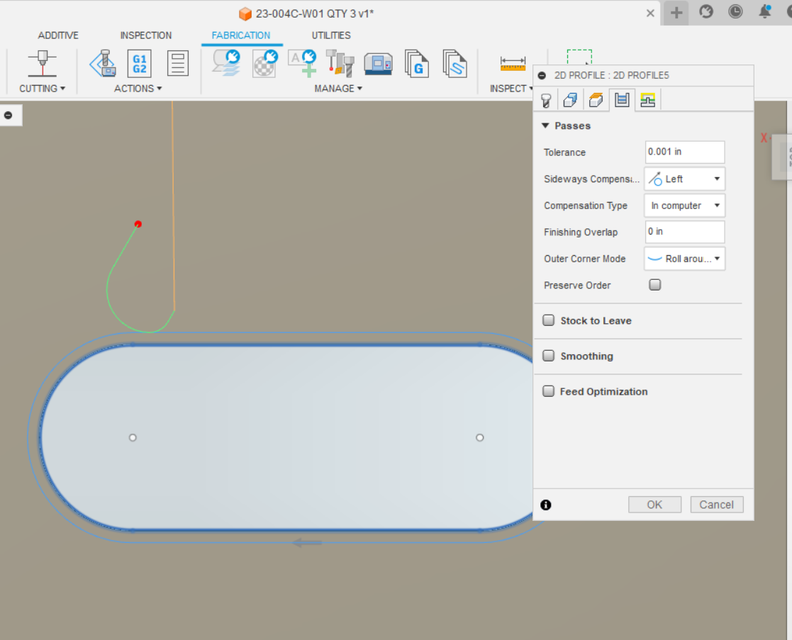
Ok I have the one sheet all set. Now I need to cut 3 others. Same size, just a different slot layout.
I have one setup that worked fine, when I went to the 2nd setup on the (on the right end as viewed in fusion) I for the life of me cant get the cuts on the inside of the slots. I have no idea why. Would you take a look at this when you have a min.
thank you
23-004C-W01 QTY 3 v1.f3d (187.5 KB)
@Knick - I took a look at your file. Two things needed to be changed. I set sideways compensation to Left. I then reversed the profile direction (either thru the chain selection menu or clicking the Red Arrow.)
For esthetics, I also changed your nozzle diameter to match the kerf in Tool 2.
Take a look. I think this is what you were after.
23-004C-W01 QTY 3 v1 (mod).f3d (188.0 KB)
3 Likes
I had comp set to left weird.
I could not get the arrows to flip for some reason. Maybe the order you did it?
I am going to try again and see what happens
Thank you very much for doing that, I really need to know why I could not get it set like I needed it.
Here it is set to left
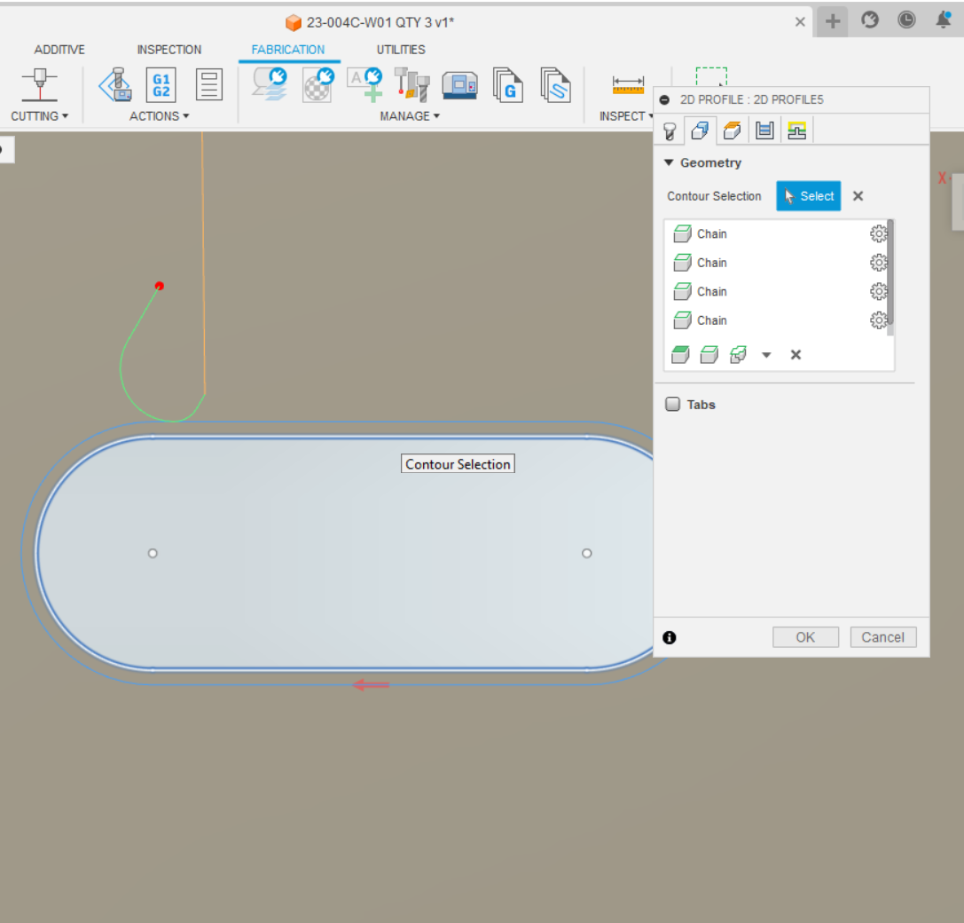
arrow seems greyed out, cant move it
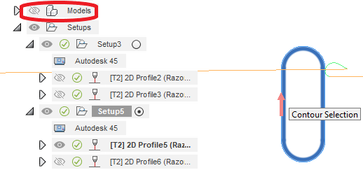
I was having that same trouble but this is with “model” visibility on:
Then when you turn “model” visibility off, hover over the arrow, it jumps out at you:
2 Likes
If you rotated your model view 180 degrees you should have been able to click the arrow. This is one reason to keep the model in the same planes as you want to cut in. I had trouble with everything looking like it was goin to cut the wrong rotation but had my Z opposite of Z in the WCS so I was programming it looking up from bottom not down from top even though the model was top view. I don’t have access to my computer with me to verify that is happening to you.
2 Likes
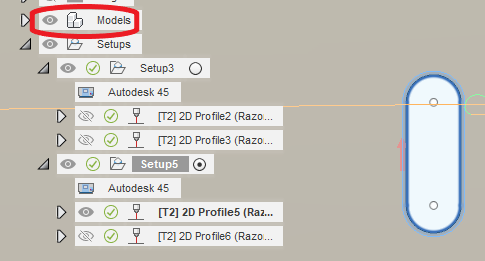
Ok So I went back in to look at this again. I looked and Model was off. I looked and everything I was trying to change was just the way I wanted it.
Then I remembered There are 3 of these panels and one of them in the drawing is turned 180 degrees. While I was setting up the cut paths, I got the one half done and was going to do the other end and I thought I better flip this over and make sure it looks right. I never flipped back and that kept me from getting the paths to looks right.
I was looking at it upside down.
Thank you very much now I just need to remember that for next time it happens
4 Likes
Ok so I cut one panel and it came out pretty good.
I loaded the sheet like normal and let if hang off the front side of table and made the first cut.
I them marked the sheet at the half way point and Slid it ahead until the 1/2 way mark was at my home position for X and did the second cut.
The large slots are not perfectly in line from cut #1 to cut #2 but they are with in 3/16".
Not as good as I would have liked it but you really don’t see it.
Just 3 more to go
The sheet I received was a 1/4" out of square so I’m not sure how that might have affected my cuts.
It measured right on for length and width,
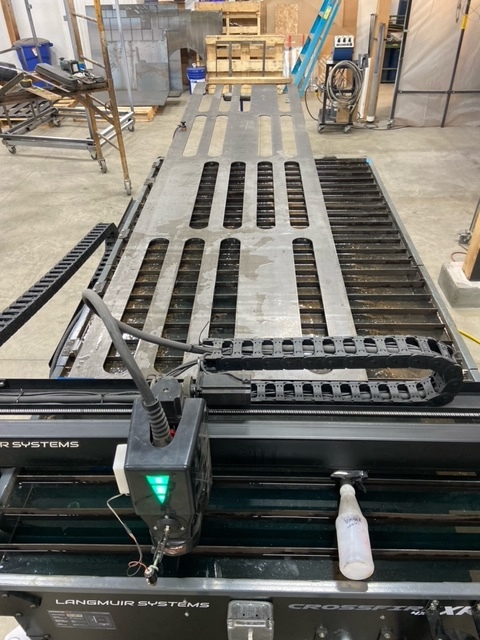
just out of square.
1 Like
I found the issue just making some screen shots brb

This center dividing line you used for the WCS in setup overhung the material a little bit.
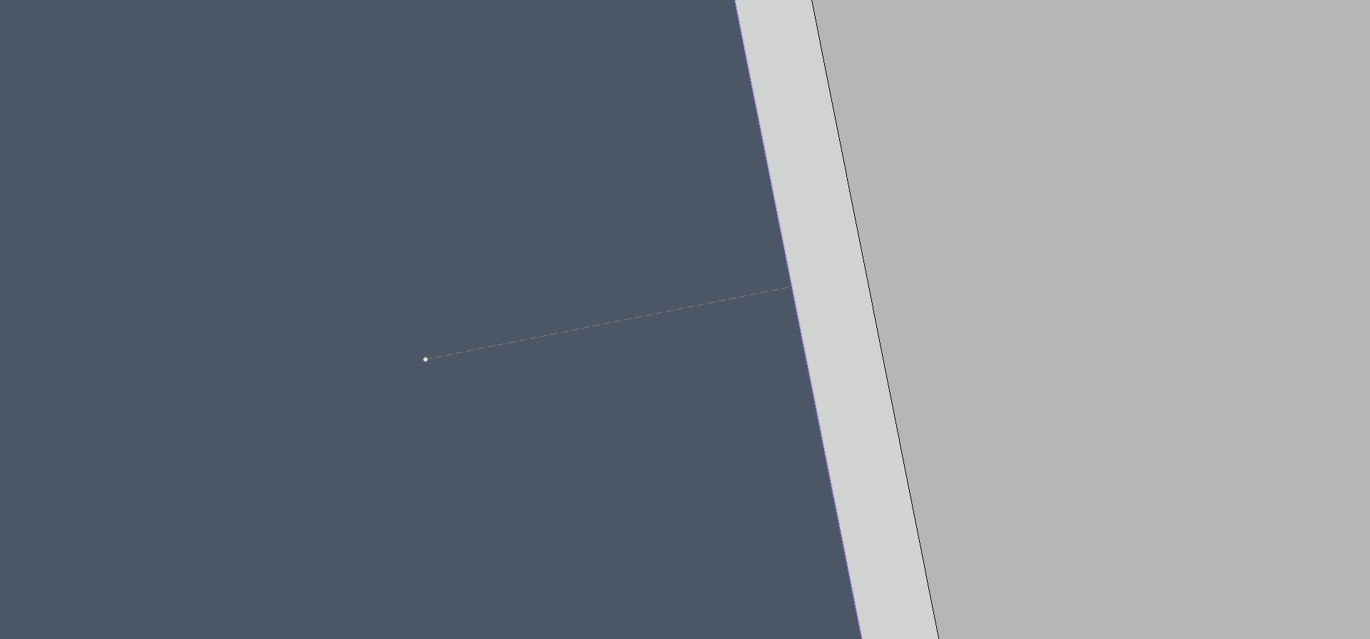
but very small it would not account for the whole 3/16"
I dont see how this would effect the slots? I was thinking anything that was off was me not keeping the sheet perfectly inline.
Weird thing the slots did measure the same down to a 1/16 from the ends. (if that makes sense)