I was aware of rotating and setting origin, but have never check points. I am going to do a lot of checking for sure. Material is coming next week so I will begin with just seeing how I will load it and then see how I will move it forward after the first cut. I am not going to rush, the plate was pretty pricey and and there will be no finish so no way to repair anything.
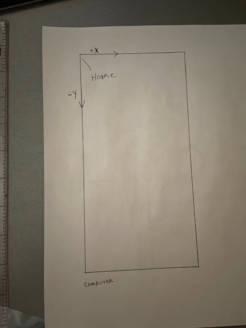
Here is the Home for the XR
See attached File:
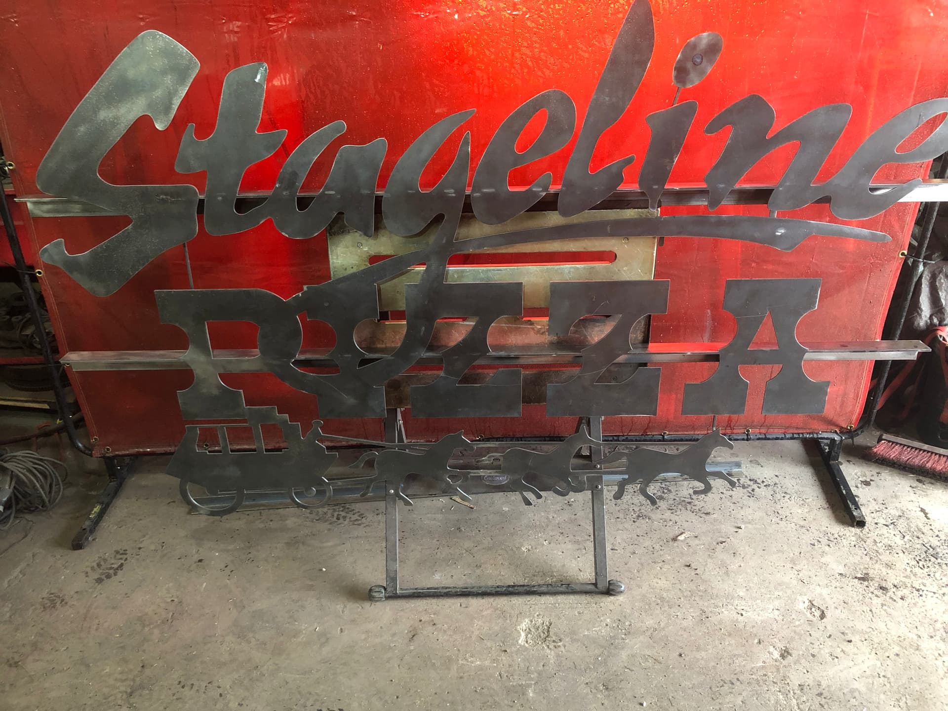
part is 36"x154"
23-004C-W03 QTY 1 Rev1 v1.f3d (213.9 KB)
1 Like
Really though you should never have to go back to design and move the object origin to correct your positioning in manufacturing.
Your project origin and your origin for your work coordinate system (WCS) are two totally different points that are separately defined. Fusion 360 when generating code only looks at the work coordinate system (WCS) from the setup in the manufacturing workspace.
The only reason we try to line up the work with the design origin is cuz then you don’t really have to think about it when you get to manufacturing because the default will be that position.
How and where are you to find your box point origin in the work coordinate system is key.
4 Likes
Ok maybe I said that wrong. There have been times when I changed the origin with firecontrol, when I had something goofed up in fusion.
I might need to dig deeper to under stand this.
1 Like
This is how I would program it. On an index cut I program from the sketch and not a solid body so I can break the lines where i will have my index. on my Pro I do it at 32.5". For you I did it a the 77" that you wanted. I went back into the design environment and added a solid sketch line at 77 inches. I also rotated it the so it is in line with the table for easy of keep track of like @TinWhisperer posted. After that, with nothing selected I right clicked on the sketch in the browser, not the actual sketch itself, and pick the slice option, then click the line that we added at the 77" mark. this breaks the lines at 77’ so we can use that as the origin for the second cut. Also if you were cutting the outside profile it would set it up to program the lines in the open contour section on the 2d profile.
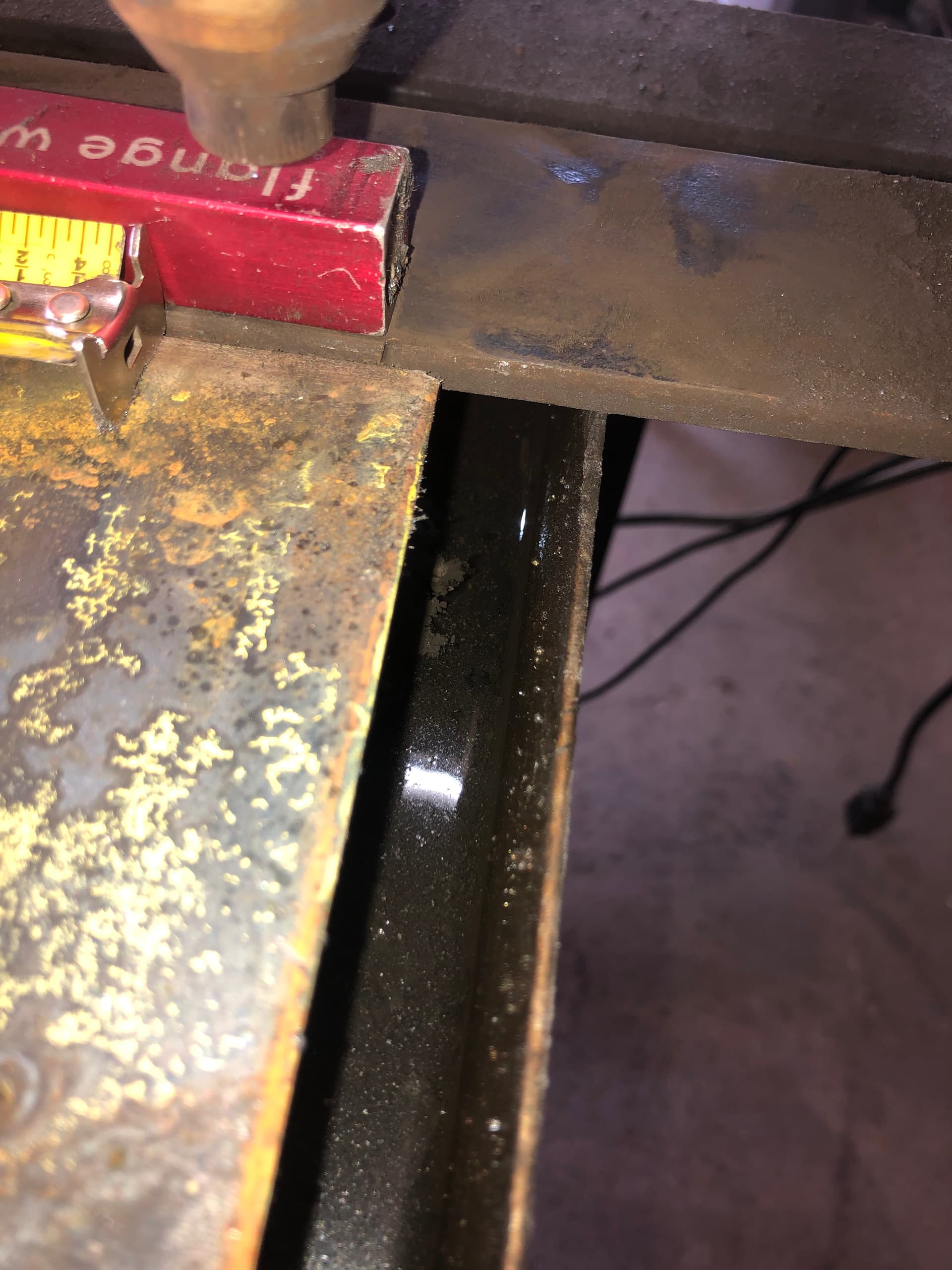
I set the stock to the actual size. I use a fence I made that runs up the Y axis on my table so I have a constant zero for Y. This way when stock is set to fixed size it will be in the same spot on the Y each time and you can focus on just the x axis.
Slot index cuts v1.f3d (243.5 KB)
check the speeds and feeds. I left them at what opened in your file and did not change them as I run a different plasma cutter.
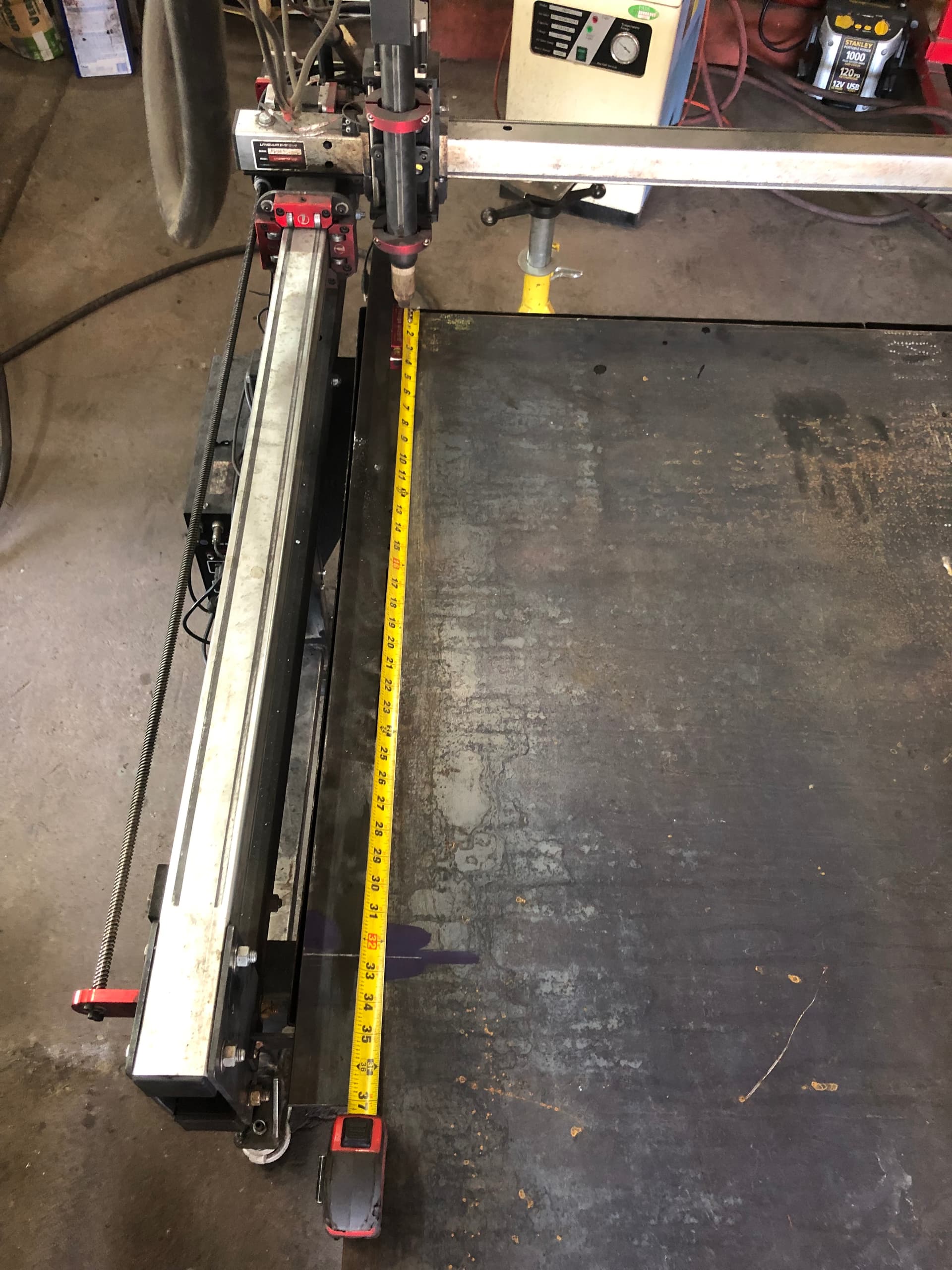
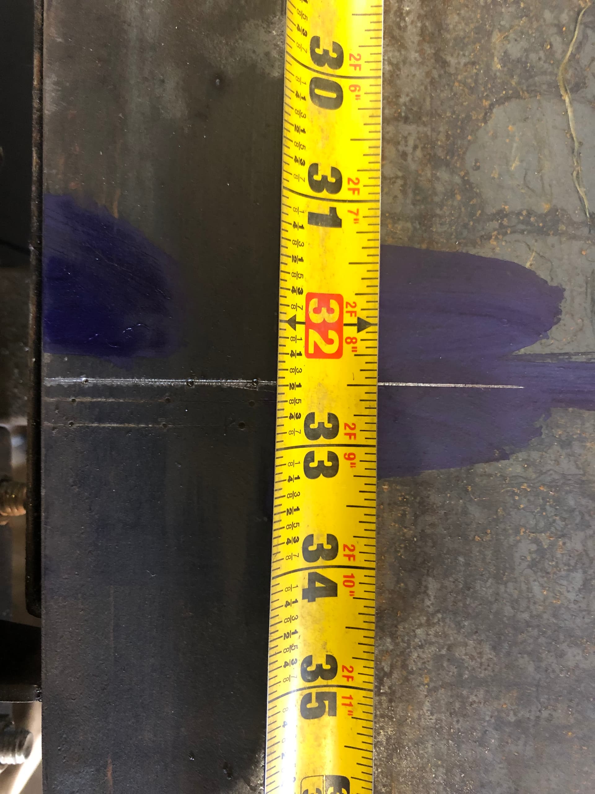
Here is my last index cut. It’s 3 programs which is 2 moves after the first cut program 81" in the Y plane. I have my origin set at the home position then measure down the 32.5" and scribe a line on my plate. I have the zero/home portion scribed on my fence. I run first program then slide the plate down to line up scribe lines and repeat.
5 Likes
Ok here are the two files I have came up with, I did do a dry run and both seem ok. @Bigdaddy2166 I still have 34 more dry runs to be safe but thought I would see what you guys think of the two files.
The 1st setup (1st NC file) will will run and cut the first half of the sheet and stop. I will then move the sheet ahead and line my index mark (at 77" 1/2 way mark on sheet) up with my X home position.
At that point I will run 2nd setup (2nd NC file) and that should cut the 2nd half of the sheet.
Let me know what you think
23-004C-W03 QTY 1 Rev1 v3.f3d (212.2 KB)
2 Likes
I’m watching this thread to see how you make out. Big Daddy is rooting for you!!!
3 Likes
no files uploaded but i believe in you guys
2 Likes
I might need donations if this does not work out. Maybe a go fund me ![]()
1 Like

You got this:grin:![]()
![]()
You are scaring me a little bit. I am thinking you need to get two sheets of 26 gauge to do your first burn.
1 Like
That would be cheating wouldn’t it?
DO NOT CUT THIS FILE @knick
in your file you are cutting the wrong direction . ( Profile 1,3,4 )
Counterclockwise for inside shapes
Clockwise for outside shapes
Sideways Compensation LEFT must be selected

You will want some feed optimization added to these tool paths. (Profile 2 & 3 )
in Profile 4 you are missing your retract height from the heights tab in the 2d profile menu
4 Likes
I see what you did. you lowered the overall feed rate for these smaller opening . Smart move ![]()
2 Likes
You wouldn’t need to tell anybody!!! ![]()
1 Like
Looks like you need to change your sideways compensation in set up T2 and both T3 and T2 in setup 2. I believe it should be set to left compensation. Is that what you see @TinWhisperer?
2 Likes
I corrected this the other day, I must have closed it with out saving all fixed now
Ok here is the updated file.
I checked and a sheet of 16 ga to test on, is $125. I am going to play with this over the week end,
but I am thinking I might just wing it. $125 is alot to just scrap it.
23-004C-W03 QTY 1 Rev1 v5.f3d (211.8 KB)
Let see if you catch anything else
1 Like
Totally agree with this addition. It makes nearly any set-up easier.
1 Like