Just make my torch trigger mod for Harbor freight Titanium 45. The leads can be fed through the front vent easily and FYI the two trigger leads are the two on the Right-hand side of the white plug at center of pic. 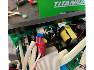
2 Likes
Hi, I just picked up a Titanium 45 and didn’t notice there was no trigger input until I took it out of the box. Is there a detailed description on how to plug one in like you did, and where to get whatever is needed to accomplish it? I have an old hook up wire from a Primeweld, but there’s no place on the cutter to attach it.
Your crossfire Pro came with the plastic clamps to splice into the wires for the trigger, and the plug that goes in to your control box at the table. you will need 2 wires 10-15 feet or more (even speaker wire would be fine for this purpose, ). Take the top off your plasma, and splice into the wires indicated. Once this is done you can test it by just touching the wires together to fire the torch. On the other end of your wires connect to the stripped leads of the control box plug. I fed my wires through the front ventilating slats on the plasma, looks good, works great
1 Like
Thanks for the help on this. I didn’t get any plastic clamps to splice with, but I can get those. I have the correct hook up that goes into the Crossfire control box. On the other end, I’m just not sure which lines to splice into for the plasma cutter. There are two double lines (white sheathing) going into the same clip on the motherboard. Do I splice into one of each of the sheathed lines, or splice both lines into the lines that come from the same sheathing? Do the wires left to right 1,2,3,4 matter, or just tap into each white sheath?
Wow, sorry, I think you answered my last entry in your first post. It looks like my reference to lines 3 and 4 match your description in the “two on the Right-hand side of the white plug”. Thanks so much!
1 Like
When you say its one the right hand side how are you looking at it? It looks like you spliced into the left wires from the picture.
Sorry about the picture, its as stated, from this view. The white plug, the two wires on the right side.
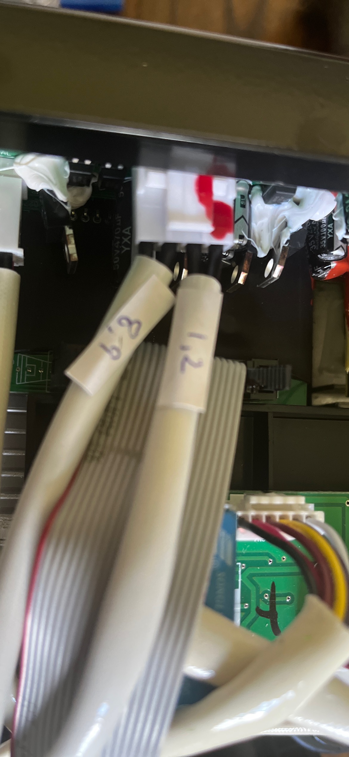
Just trace the wires from the euro connector pins 1 and 2 are the trigger, pins 5 and 6 are the pilot arc and pins 8 and 9 are the safety or cup pins.
2 Likes
If I trace the wires from the plug to the motherboard looking down which wires do I use?
And it sounds like I just tap into both wires in the same sheathing
Thank you in advance for the clarification.

For anyone reading thru this thread… the correct trigger wires come from the pins 1 and 2. Do not use pins 8 & 9.
2 Likes