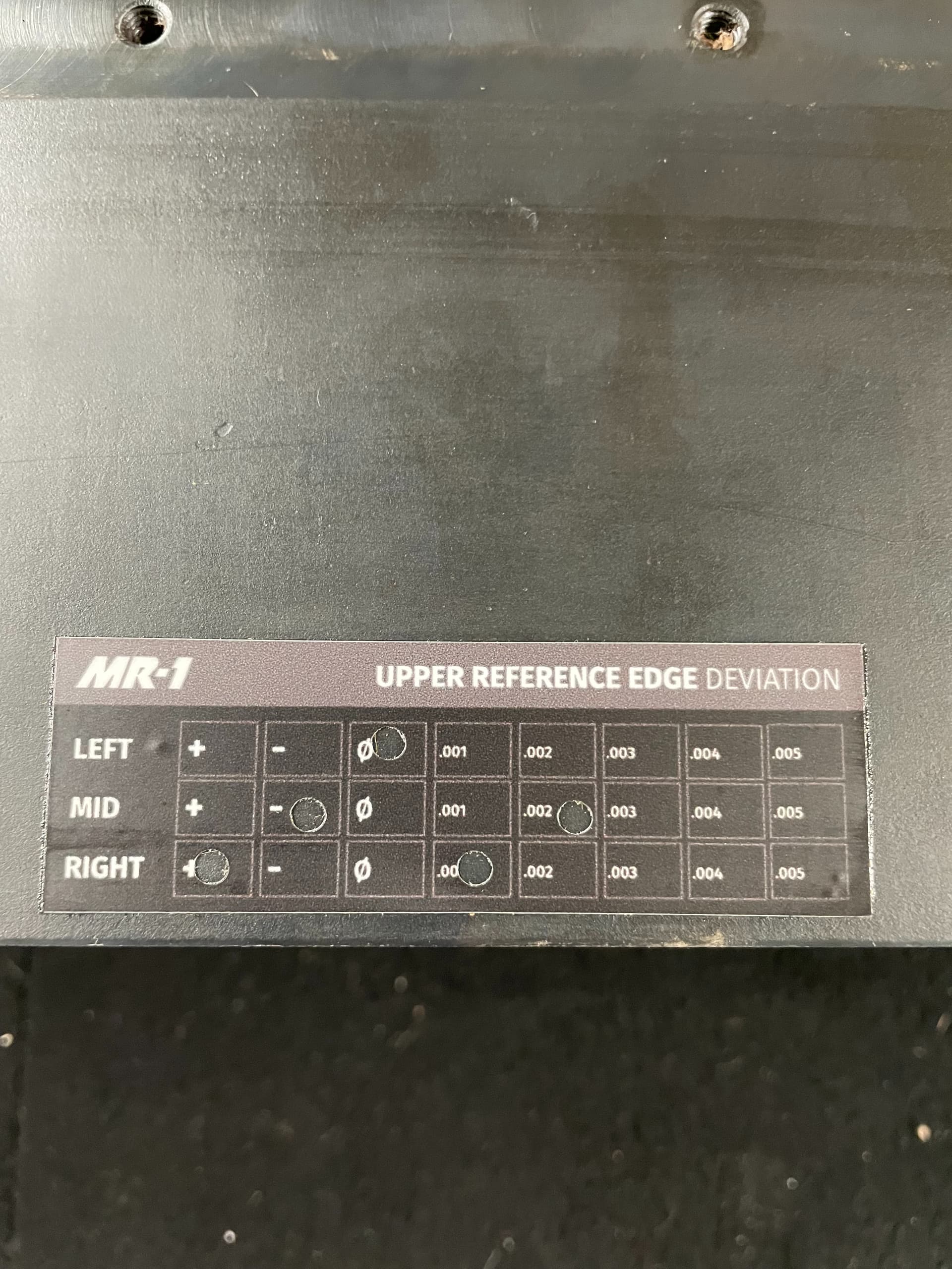
I’m having an issue when I do a light check when the spindle is mounted to the gantry. According to the shim calulator I should be using zero shims. I have attached pictures to show the issue I’m having. Anyone run across a issue like this?
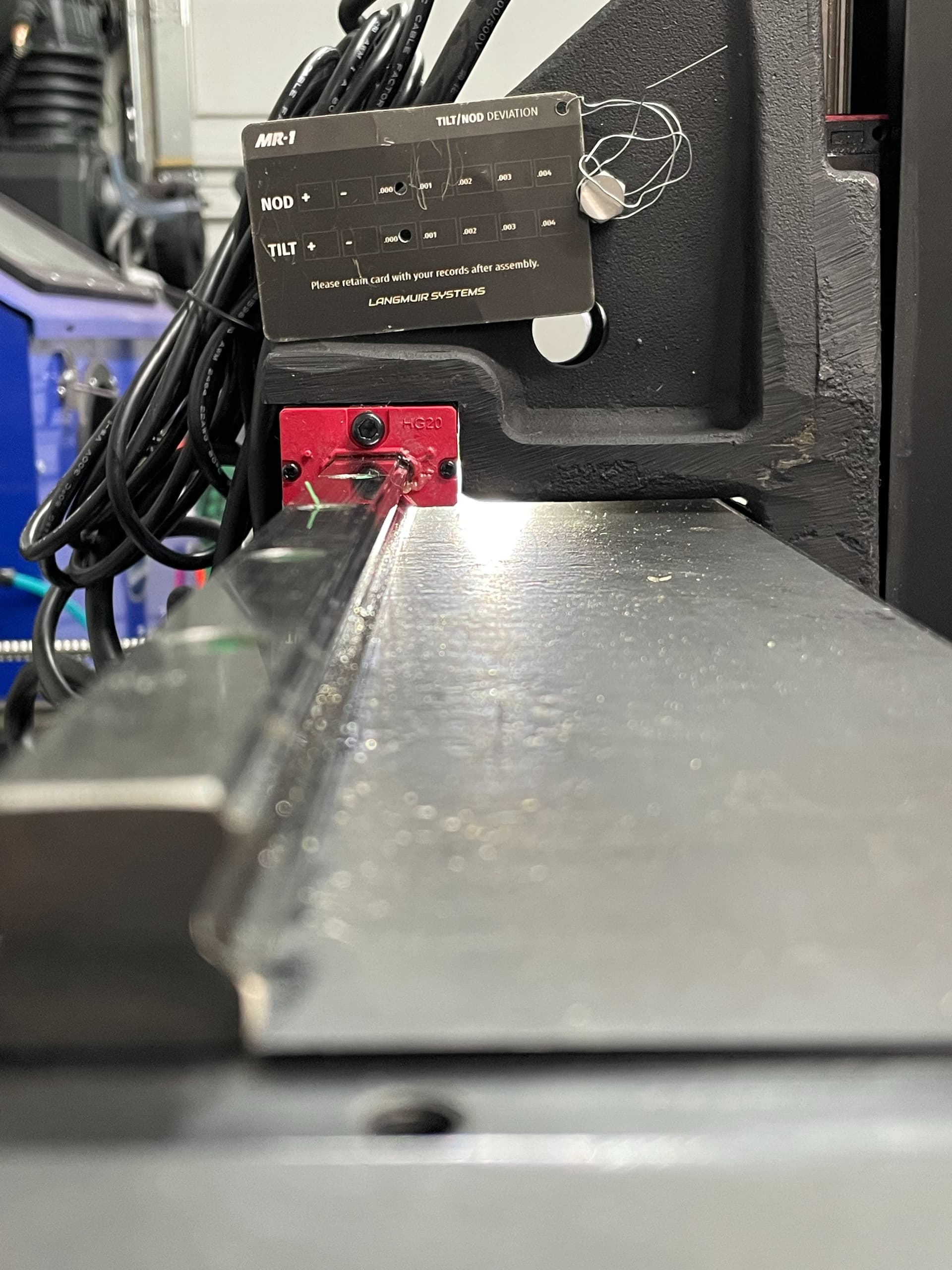
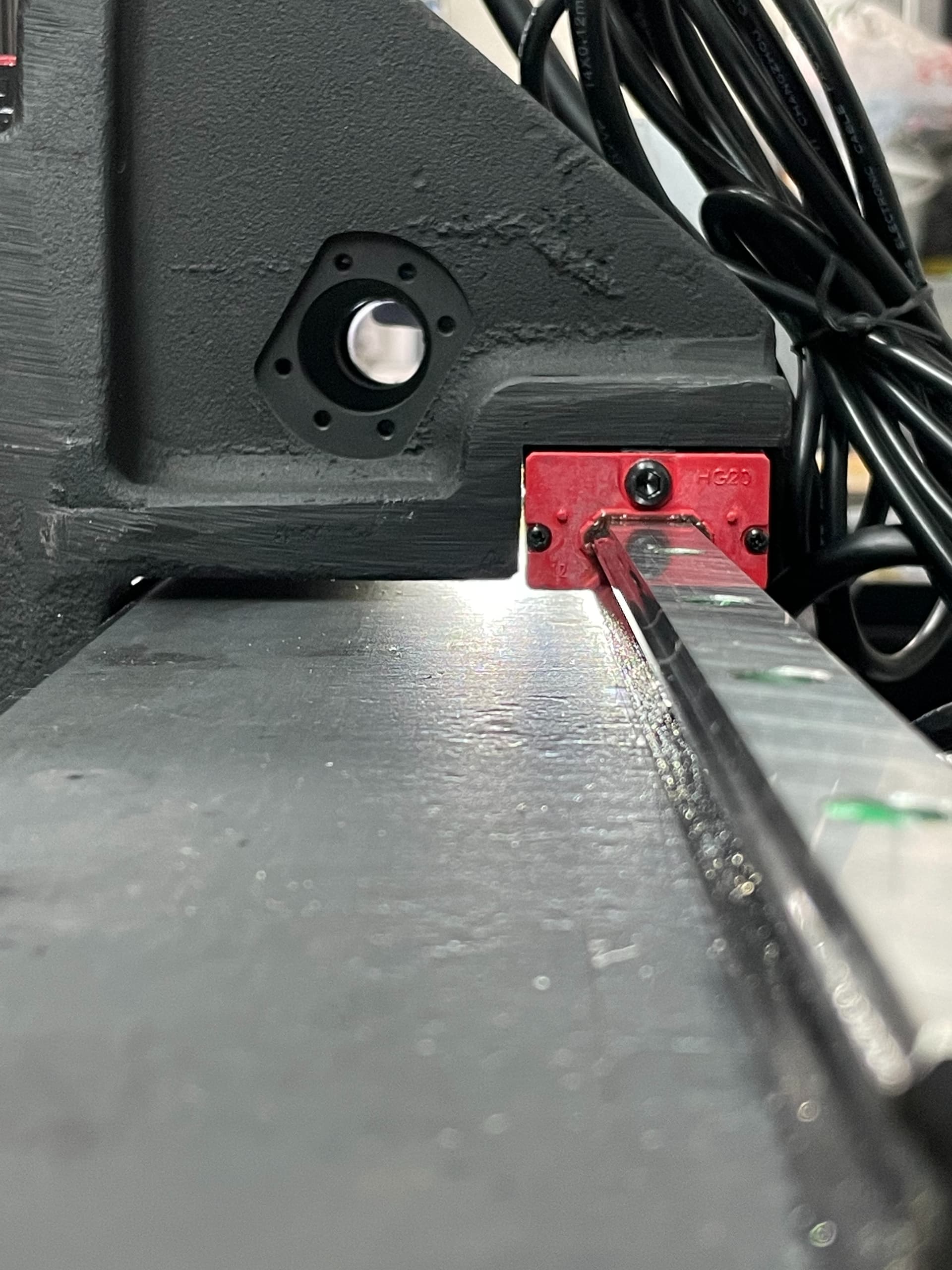
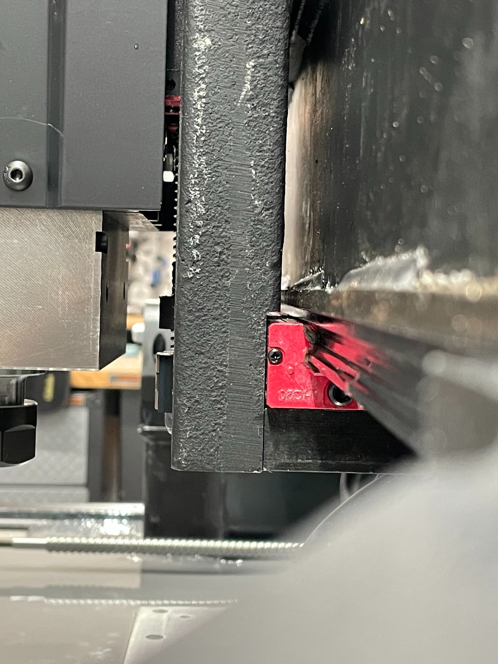

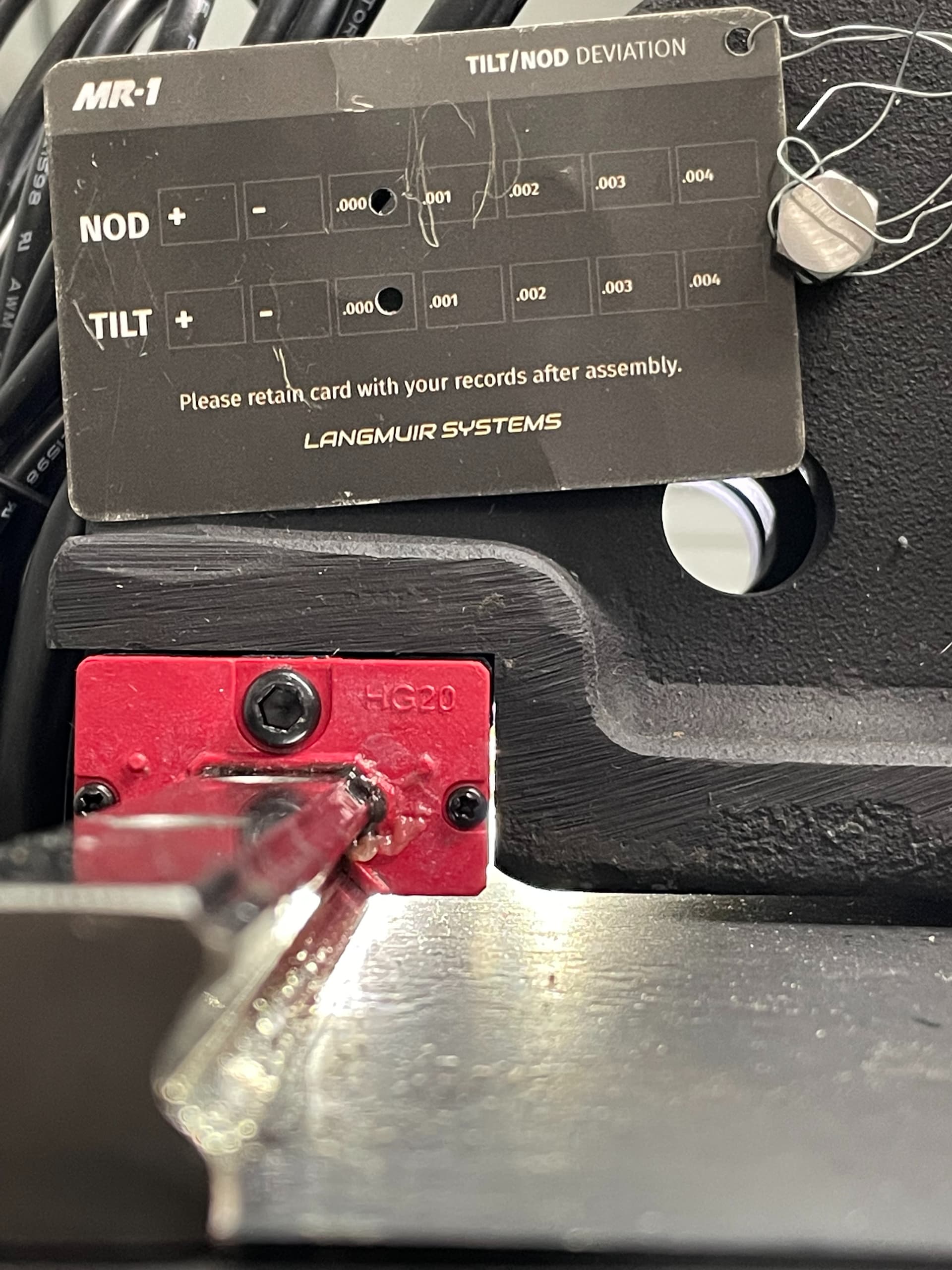
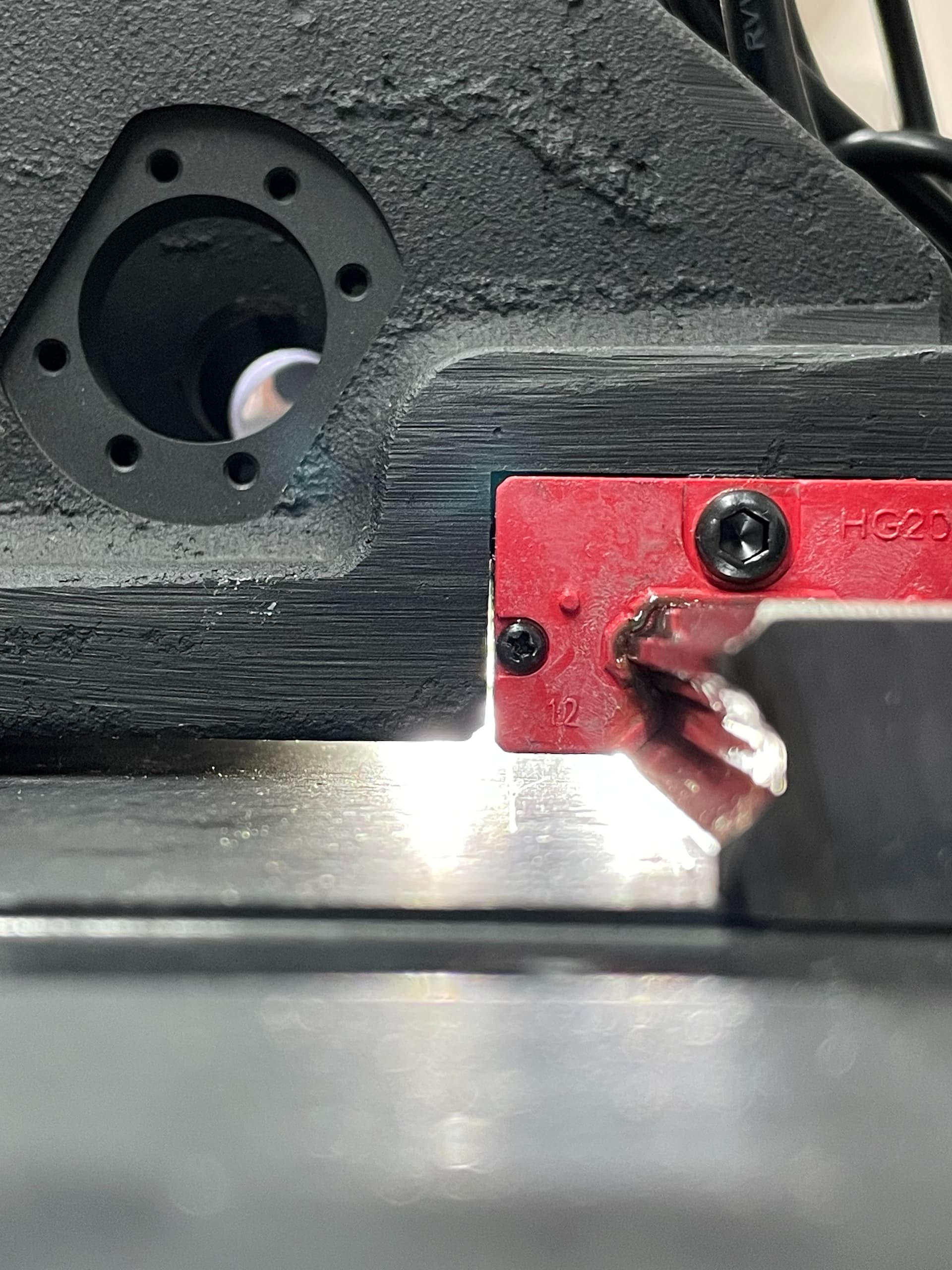
Looking at the last two pics it appears the contacts are good?
I’d recommend proceeding with assembly and facing the baseplate. There’s a step where you’ll measure Z alignment directly and shim as needed to adjust it.
1 Like
If i remember correctly mine looked similar, I think only about the top 1/4 inch of that linear bearing is precison ground so anything below that wont contact or might show an air gap. either way mine was similar and my machine has been running great !
1 Like
Thanks guys, I’ll proceed with the build.
I had a similar problem with the space between the bearing and Z axis. Turns out the casting had a high spot at the inside corner by were the x axis slides by. Had to remove the Z axis and use a grinder to remove a little material from the casting.
Dave
Intresting. I didn’t notice a high spot on ine ut did run a stone on all surfaces to remove and burs or high spots. I’m at the limit switch install parts of assembly, I guess I’ll see what happens as I get to the tram part.
I decided to put some feeler gauges on the left and right side of the upper bearing block after reading about some of the issues with the Z casting being out of spec. Should I still proceed with the build and facing the base plate? Thoughts?
Left side: .30 mm (.011”)
Right side: .40 mm (.016”)
If you are sure it is as fully seated as it can be and it still has that gap, you can build a shim stack using shim stock (a huge pack with all sorts of sizes is pretty cheap) to build up that area. The bearing blocks aren’t perfectly straight on some of them, mine was off quite a bit, I just built up the sides that were low, making sure to not put too much and create a new high spot. So if you can get a .011 feeler gauge in, maybe try a .010 shim on that side. Also my z casting was one of the messed up ones, it wasn’t that part that was messed up, it was the z rails surface that was twisted. Also looking at your pics I think you are ok, mine was straight up a big gap all the way up that face, yours blocks the light in the area where they make contact. Also, how far can you put the feelers in? the reference surface doesn’t start for maybe a half inch, so the feelers will fit in there on every machine, its if you can get a .011 feeler in between the ground surface on the bearing and the carriage, then you have an issue and shimming may help.
1 Like
Would you happen to have a link to the assorted shim sizes? Maybe something like the link below would work? I went back and doubled checked to make sure I was hitting the gound surfaces with the feeler gauge. Looks like only a .002 differance between left and right.
Did LMS get you a new casting?
Left side: .07 mm (.002"")
Right side: .10 mm (.004")
I was using feeler gauges too. The surfaces seem to be angled to each other (at least on mine) and as I ran the feeler gauge higher up the ground face, it would get tighter and pinch the gauge. I ended up having less than 0.0015 (my thinnest gauge) though the gaps looked horrendous visually. But still ended up with 0.012" shims in the bottom to get tram close (langmuir calculator said 2 bottom shims only).
1 Like
That’s what I was noticing as well. Calculator for me says zero shims. I think I’m just going to face the base plate when I’m at the point and see where I need to add shims.
I partially surfaced mine, I’m getting ready to do another pass tomorrow with a lot of adjustments made. I’m going to check everything again and readjust as necessary, and if I can get close enough for my liking, I’ll finish the surfacing and call it good.
Good luck. Let us know how it turns out. I may steal your idea and do a partial surface as well.
those would work, you probably don’t need stainless if you wanted to save a little money, but either way those would work. They are sending me a new casting, just taking quite a while. If you have only a .002 I would forget about it haha, as long as the casting is making good contact on a good chunk of the ground surface you are good, the strength all come from the top surface where the bolts are anyways, the front is just to make sure everything is running true.
1 Like
Thanks for all the help on this. Hopefully you get the casting sooner rather than later. I hope that LMS releases the nod/tram video soon. Would be good to see how they do it at the factory.
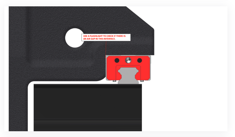
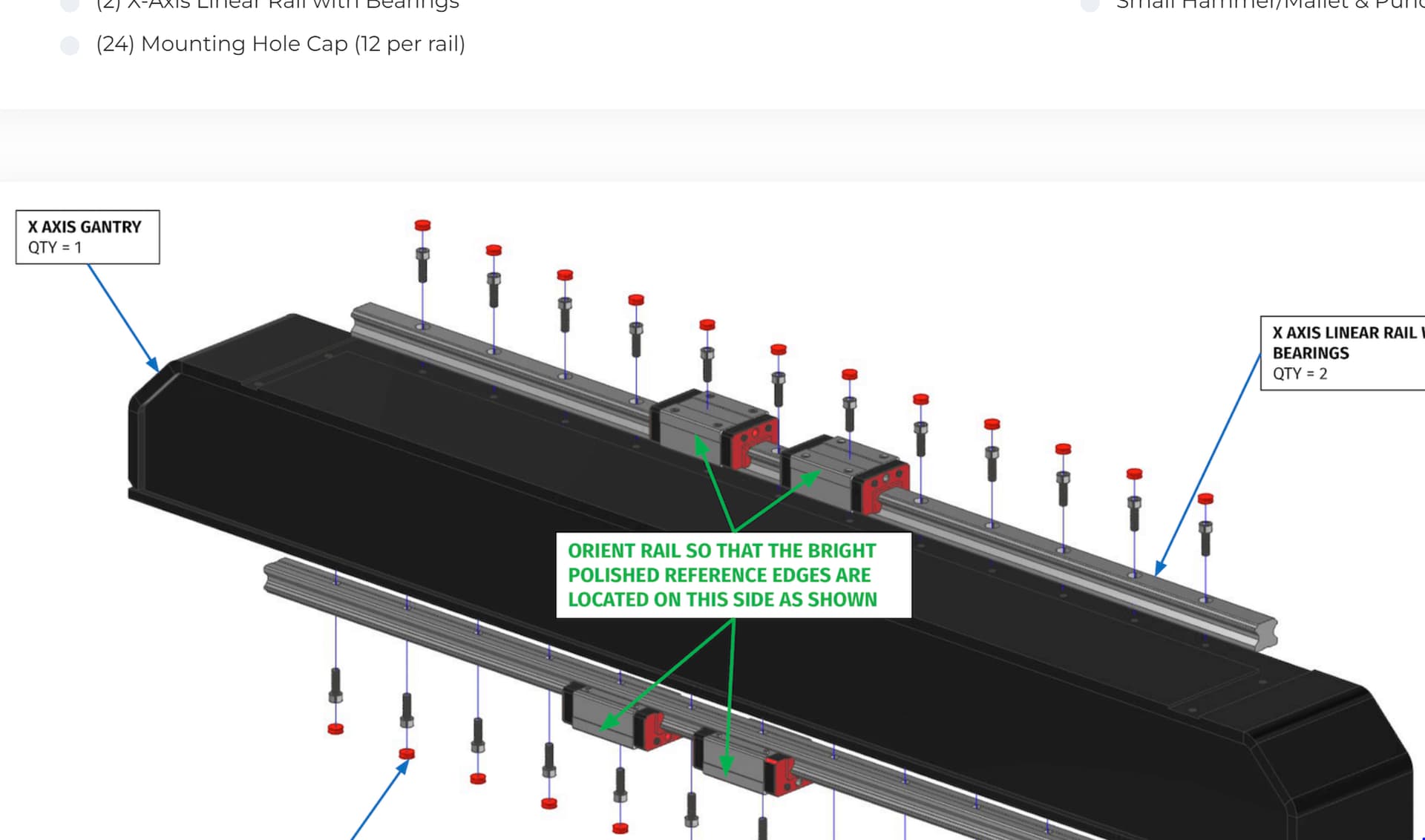
@langmuir-daniel I also have a spindle gap but its on the lower bearings. The instructions also slightly confusing to me. The blue area is where my gap is, the spindle is only resting on the black bracket below. If is is only supposed to rest on the black bracket shouldn’t the shiny edge of the linear bearings be facing to the rear so the black bracket references from a precision edge. I put the portion of instructions that is conflicting to me in a quote below

Instructions
- Thoroughly clean all of the machined surfaces on the Lower Bearing Mount. Also clean and wipe any debris off of the linear bearing surfaces and reference edges that will be mated during this step.
- Secure the Lower Bearing Mount to the lower linear bearings using the fasteners shown. When tightening the screws, ***
pull the lower bearing mount toward the front of the machine so that the back precision surface edges of the linear bearings are in contact with the ledge machined into the Lower Bearing Mount as shown.
2 Likes
I saw that too. I ignored it. I loosened the 8 bolts to finger tight on the bearing block, pushed the z carriage back, and lightly snugged up the 3 main bolts, snugged up the 8 bolts on the bearing block, then the 3 main bolts again, then finally tightened all the bolts…basically walking all the parts in to full tight attempting to keep as much contact between the z carriage and the bearing surfaces as possible. It pulls up nice and tight against the shims.
yeah that makes sense. you’d either have to do that or flip the linear rail and follow their instructions. Funny because the first time around I installed backwards.
I even double checked videos to see the bearing surfaces, and where they were shimming. I thought I misunderstood and maybe had the rail wrong myself.
1 Like