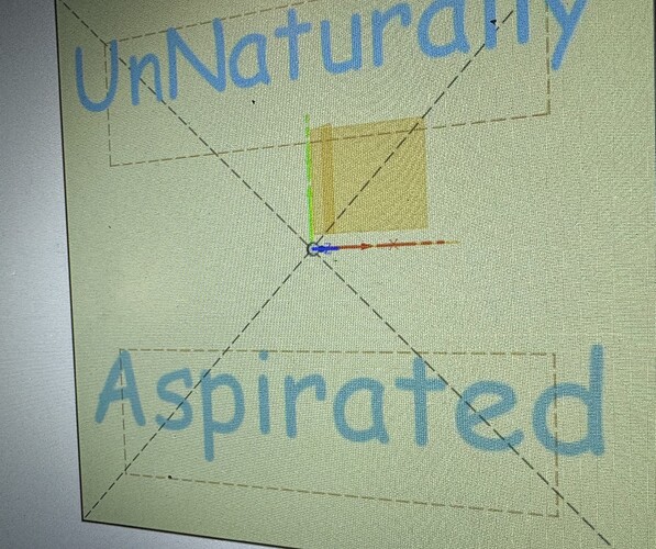
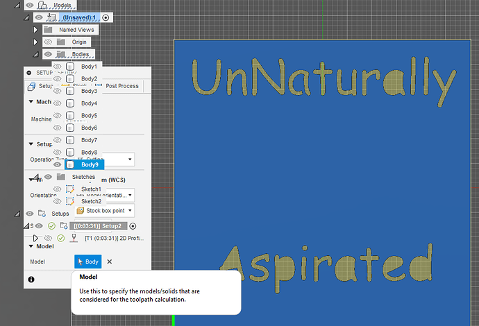
Heys guys , I’ve been machining for awhile … I’ve used fusion 360 for most of it. I’m having an issue with the lettering. The gcode is causing the machine to cut what I want on the top instead of the bottom . Is this a setup issue? When I model a sketch I click “top” and model from there ?
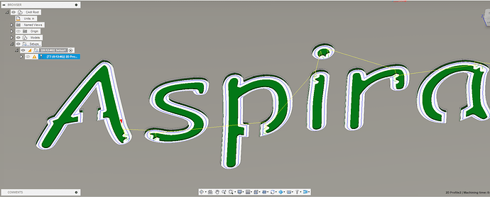
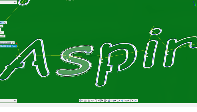
You need to put in some bridges (simple rectangles) on the closed letters - Aa p e d.
When you are setting your cut profile, you need to either extrude the field a little bit, to make it a solid body, or select sketch profile and start inside
Extruded
Start inside sketch profile
In your drawing it looks like both are cutting inside the box. which would be below the top line nof the box and above the bottom line of the box.
Is that what you want?
Are you selecting the top line of the box as what your text should follow?
What Cad program are you using?
I guess you need to show us to the top and bottom of what ?
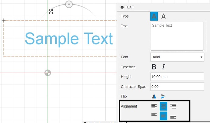
Not sure I understand the questions, but are you using the text alignment options when creating the text?
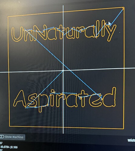
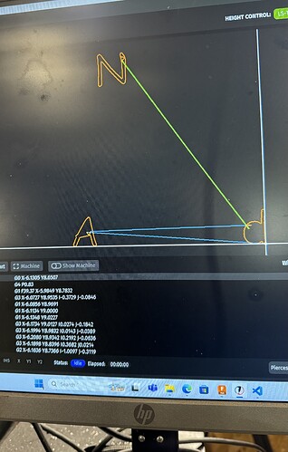
When I do a dry run … the system rapids to the bottom lettering , but it’s cutting it on the top . I’m going to load up a file shortly
You have us confused about “top” and “bottom”.
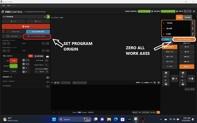
What FireControl is showing us is that you have set or by default have set your “Program Origin” to the center of your sketch/model/sign.
If you are planning to leave it that way then you also need to set your “work zero” to the center of the metal that you plan to be the actual product you are making.
This is very unnatural. I don’t know anyone that would do that. You need to pick a corner of your image [Set Program Origin] and then pick that spot on the metal that you want to represent that “corner” spot by moving the torch to that spot on the metal and then press [Zero All Work Axes].
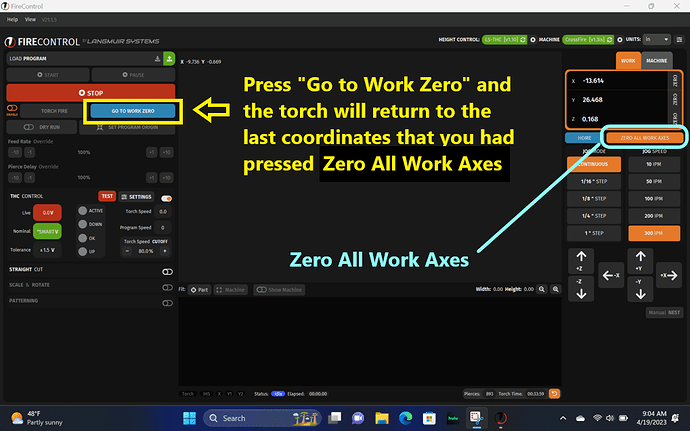
Before you press [START] you need to make certain that you are at [Work Zero] so press [Go To Work Zero].
I attached a sample … How would you set this up to cut
langmuire v0.f3d (918.2 KB)
This is a simple example … The program will start by cutting the A and D … Instead of moving up to cut the N , it rapids below … so the N get cut below the A and D
I deleted your setup. I believe your setup may have been on the wrong plane.
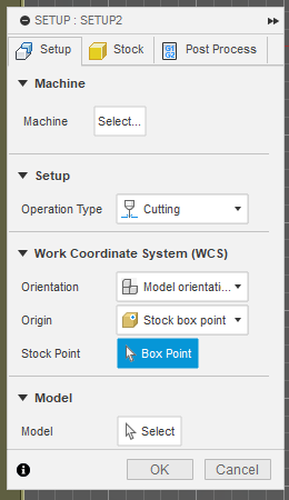
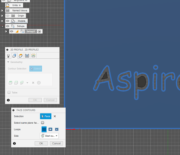
I moved the stock point to the left bottom corner:
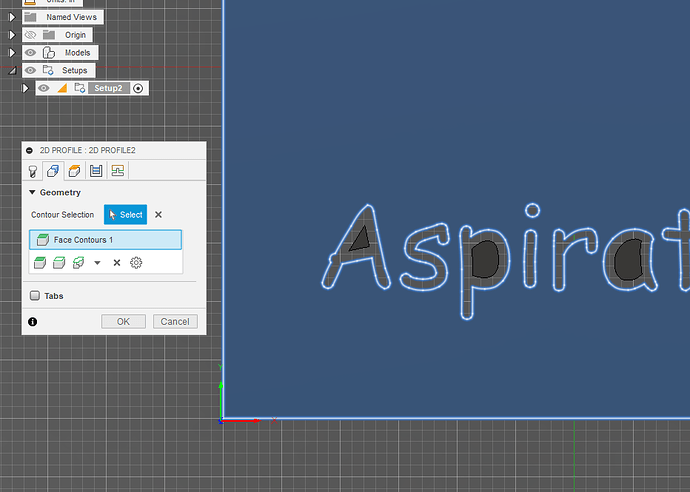
Selected the face of the body in the Contour Selection:
Completed the selection:
Now you are still going to need to go back and add the bridges that Sticks mentioned since the centers of the letters will fall out.
langmuire v0Chelan.f3d (935.9 KB)
I’ll give it a go , thanks man
You’re very welcomed.
When making bridges, you want them to be about 0.11 inches or thicker to have the strength to support the centers and survive the plasma torch cutting on both sides of it. 0.125 inches is better.
You can edited your sketch with the bridges and when you come back to "manufacturing all you need to do is regenerate the tool paths and everything should work.
One last thing: I used a very small lead in with a small finishing overlap. My technique may not be something you want to emulate in the future. I am going for success with the cut… Perhaps not perfection.
Looking further into your design, you did something interesting with lots of bodies. I then realized they were all the centers of the letters.
So lets talk about “bridging.” You will need to “Edit Sketch.” Then, you will need to “explode” the text to alter the lines. To do this you left click on the text, then right click and select “Explode text.”
Now you have the actual contours of the text elements:
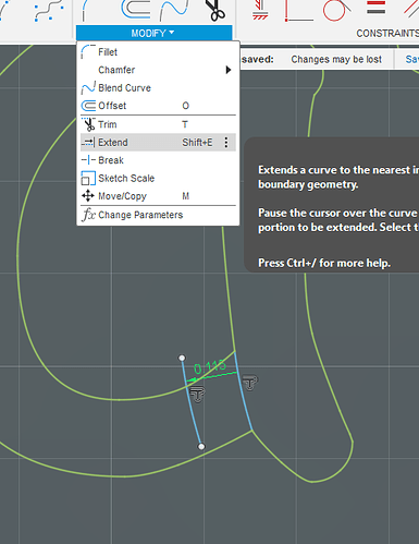
Let’s look at the “a”. I will zoom in and complete an already established line. I then select my new line and do an “offset” of that line and move it a dimension that I feel will be adequate to support the center:
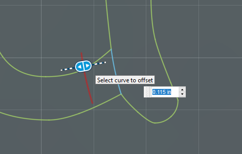
Now I extend the line if necessary:
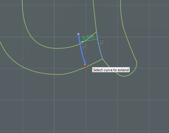
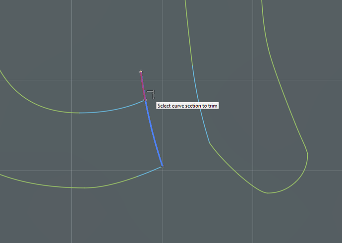
Now trim away what is not needed:
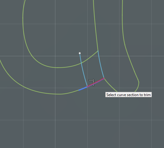
Now you can see how the profile will register the center of the “a”
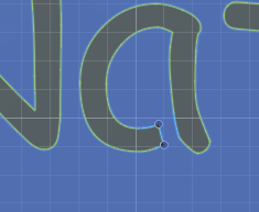
To make this work, you will really need to do all of your bridges, extrude a new body that shows these new bridges. Turn off the visibility of bodies 1 thru 8. Then go to “Manufacturing” and edit the set up because it was based on a body that we are not using. Select the new body here:
Edit the toolpath in the same way: Go to the contour selection and delete the current “face contour” and select the current body face.
Then you are golden:
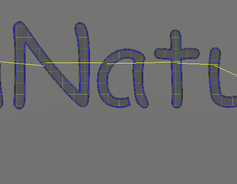
Jim you need to start some fusion online classes. you love this stuff!
I know what you are doing: You are buttering me up to get me to leave. Not going to work.
I do enjoy this and happen to have more time than most. You guys are all doing stuff, making stuff, making money.
Hey , it’s still doing the same thing , it cuts out the bottom lettering and then rapids down to cut the top lettering . So it cutting what should be on the top , on the bottom …
1001.nc (59.3 KB)
So if you did online classes you would be making money too
