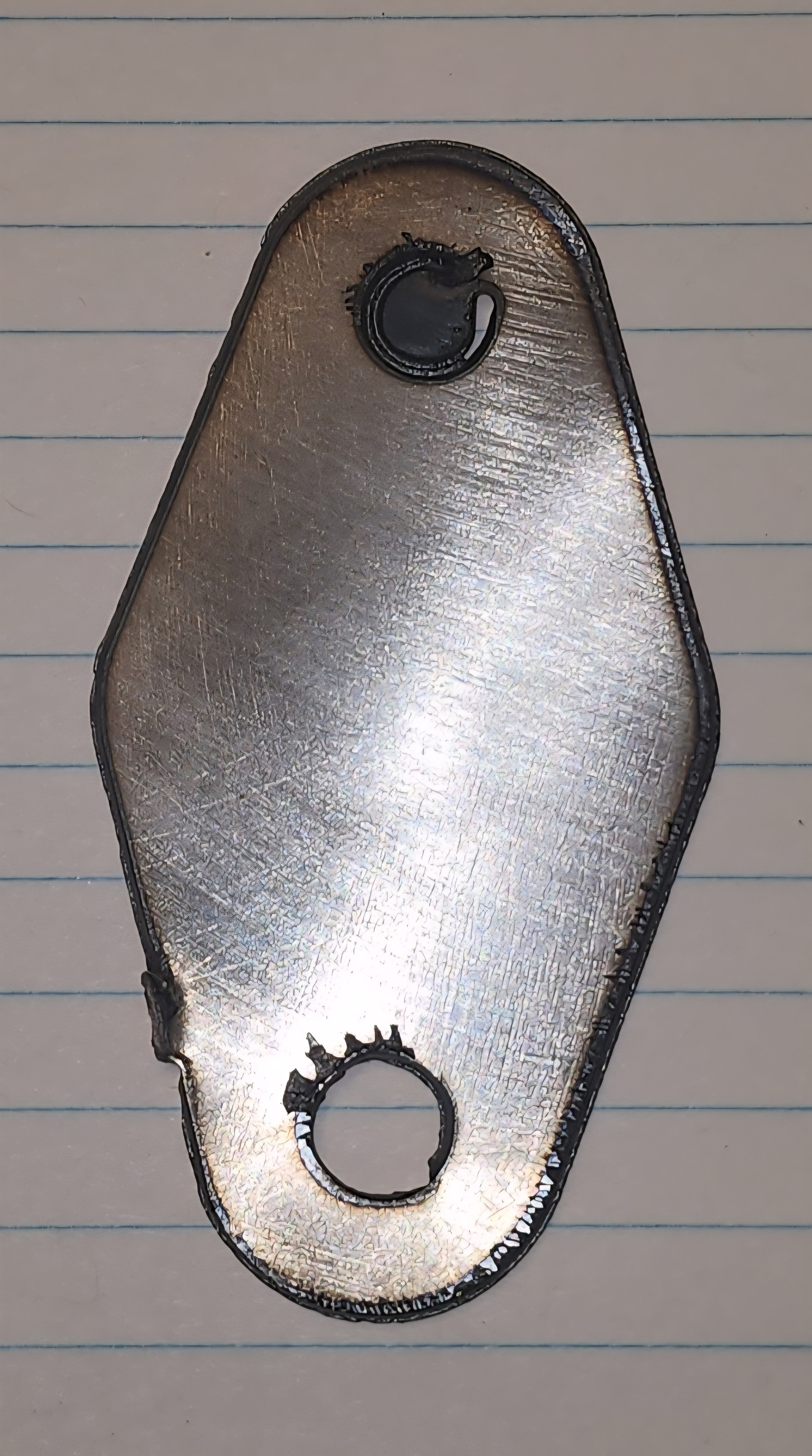
Any advice and guidance would be greatly appreciated. I am trying to cut 18 ga and for some reason some circles are not complete and there is a tab that is left even with the tab box not being checked. You can see the tab in the lower left hand corner. The competly cut circle was the first cut made. The incomplete circle was the second cut and the last cut was the outside but it was incomplete. When I run the simulation in cam and make the cutter translucent, it showes the cutter overlapping the initial cut befor continuing to the next cut and again overlapping entry point befor moving onto the final cut. It almost looks like the tab on the body is the same amount as the amount of the top circle
Try to post your NC file.
I have a feeling this might be more plasma cutter related.
Which plasma cutter are you using?
Thank you for the help. I have a everlast 62i.
If you can post the NC file that would be helpful.
Make sure the work “ground” clamp is directly on the material.
You may have a internal regulator or some kind of air issue causing this.
But if we can see the NC file then we can see if the other parameters are okay.
2 Likes
I made a couple changes in CAM and it seems to have fixed the problem. I made the changes based on an AI recommendation. The following are the changes that I have made.
-
pierce heigh
-
pierce Delay
-
cut height
-
feedrate
-
lead-out radius
I will try and post the faulty NC file along with the corrected file a little later today. I have watched hours of fusion CAM videos on YouTube and many of them say click on this and change it to that, but I have not found one that does a good job of explaining step by step what each radio button does on setup and 2D Profile. They don’t explain how adjusting a parameter affects the plasma cut in the G code. If anyone has a video like the one described it would be appreciated. I don’t know which altered setting actually fixed the problem.
2 Likes
If the code was the problem I’m sure we’ll be able to find it.
If you took your original Fusion file before you made all the changes and saved it as an f3d file and posted it it would also show us exactly what you inputted in Fusion
I have both NC files however I did not save them as F3D. I used fire control as the post processor and it saved as the default file on my desktop. I know I still have work to do to diel in this machine. I am just a little unsure what adjustments affect the cuts. My circles are not quite right and there is a little nic in the lower left of the body but I will worry about that after I start to get consistent cuts and I am confident the machine will complete a cut without leaving tabs.
1 Like
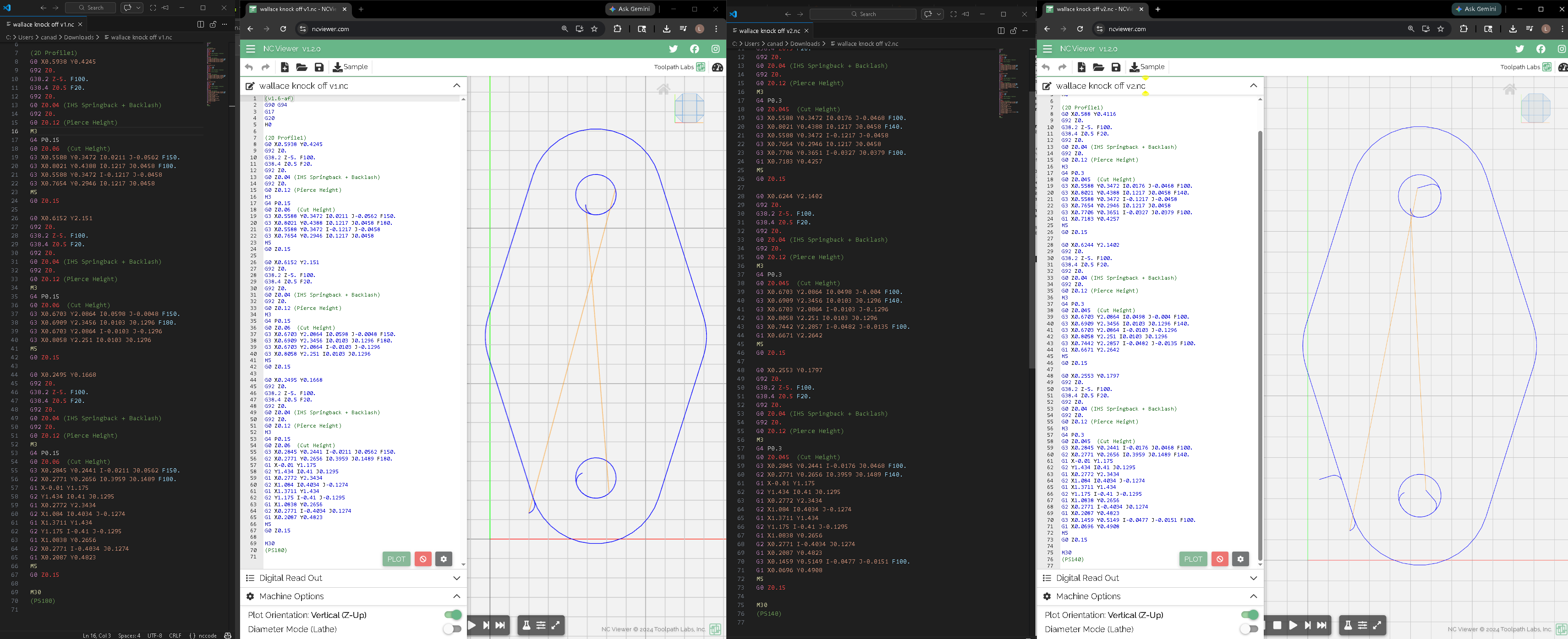
wallace knock off v1.nc (1.2 KB) this is the NC file with the error.
wallace knock off v2.nc (1.4 KB) this is the file after adjustments.
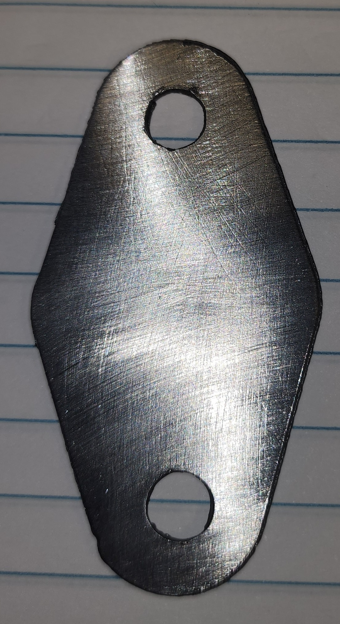
The failed cut is on the left the successful cut is on the right.
I’ll post this here so everyone can take a look at the code.
A couple notes is there is an extreme overcut setting on both of these. I normally do not use an overcut unless it’s for thicker material.
On version 1 I see you have a Pierce delay (g4) of point .15 add on version 2 you have a Pierce delay of .3 . Both of these are inadequately short Pierce delays on the Langmuir pro table. The Langmuir pro has about 0.5 second delay from the software triggering the fire relay to the torch actually firing .For 18 gauge I would start at .5. This alone would probably fix the issue.
The reason the second program was likely successful is the slightly longer Pierce delay and this will lower program speed.
What amperage do you currently have your plasma torch set too?
On this simple bracket in 18 ga you shouldn’t have to apply any added features in the 2D profile. menu. You could probably get away with the straight 90° lead in with no lead out, I would not be doing any feed rate optimization, and I would get rid of the overcut setting. With this thin material like don’t think you’ll even need a radius lead in.
Simplify the program and increase the Pierce delay. Check the quality of your consumables and make sure your machine is set to 45 amps to start. Make sure the work clamp is on the material being cut .Try again and you should be successful.
1 Like
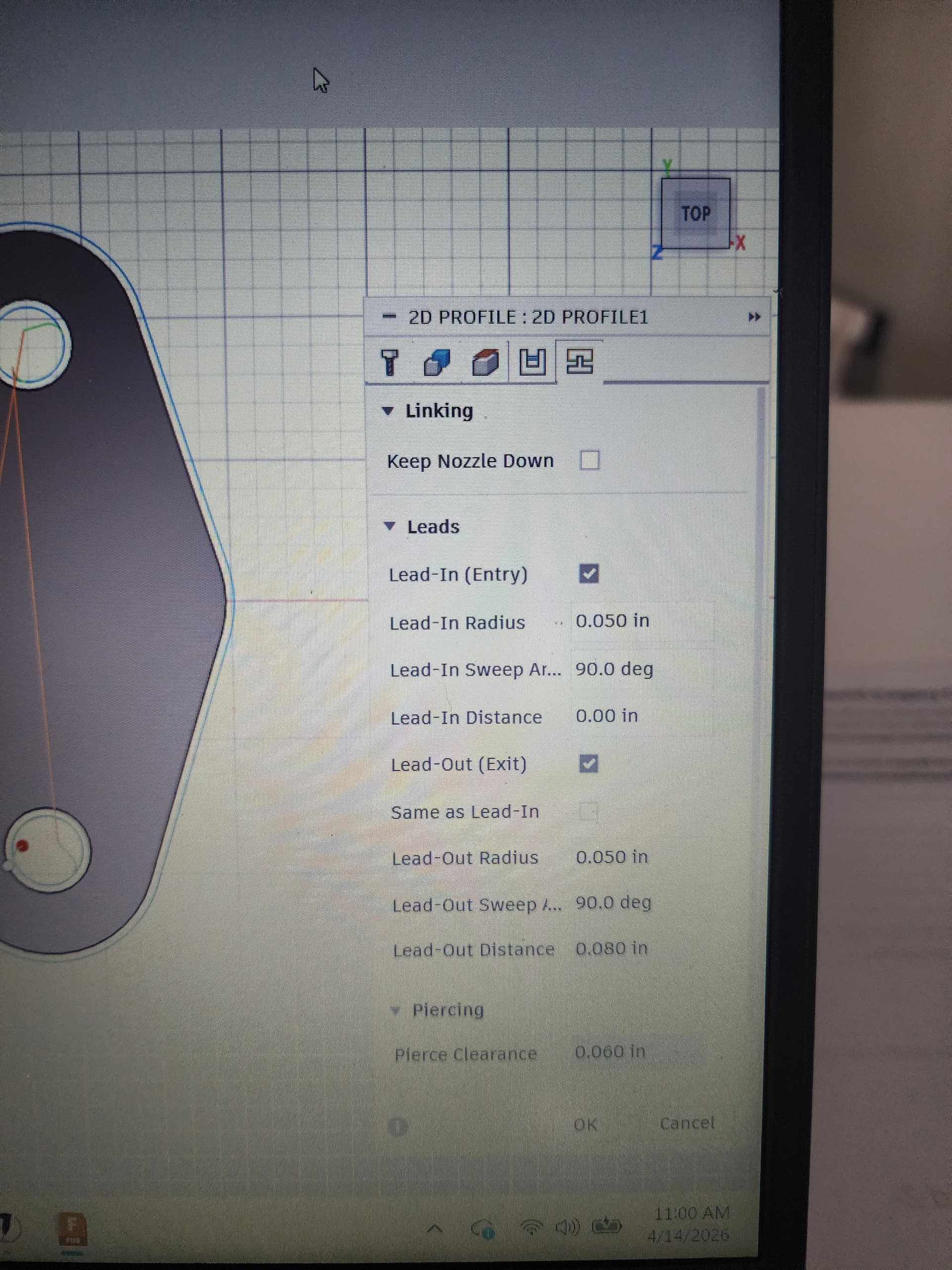
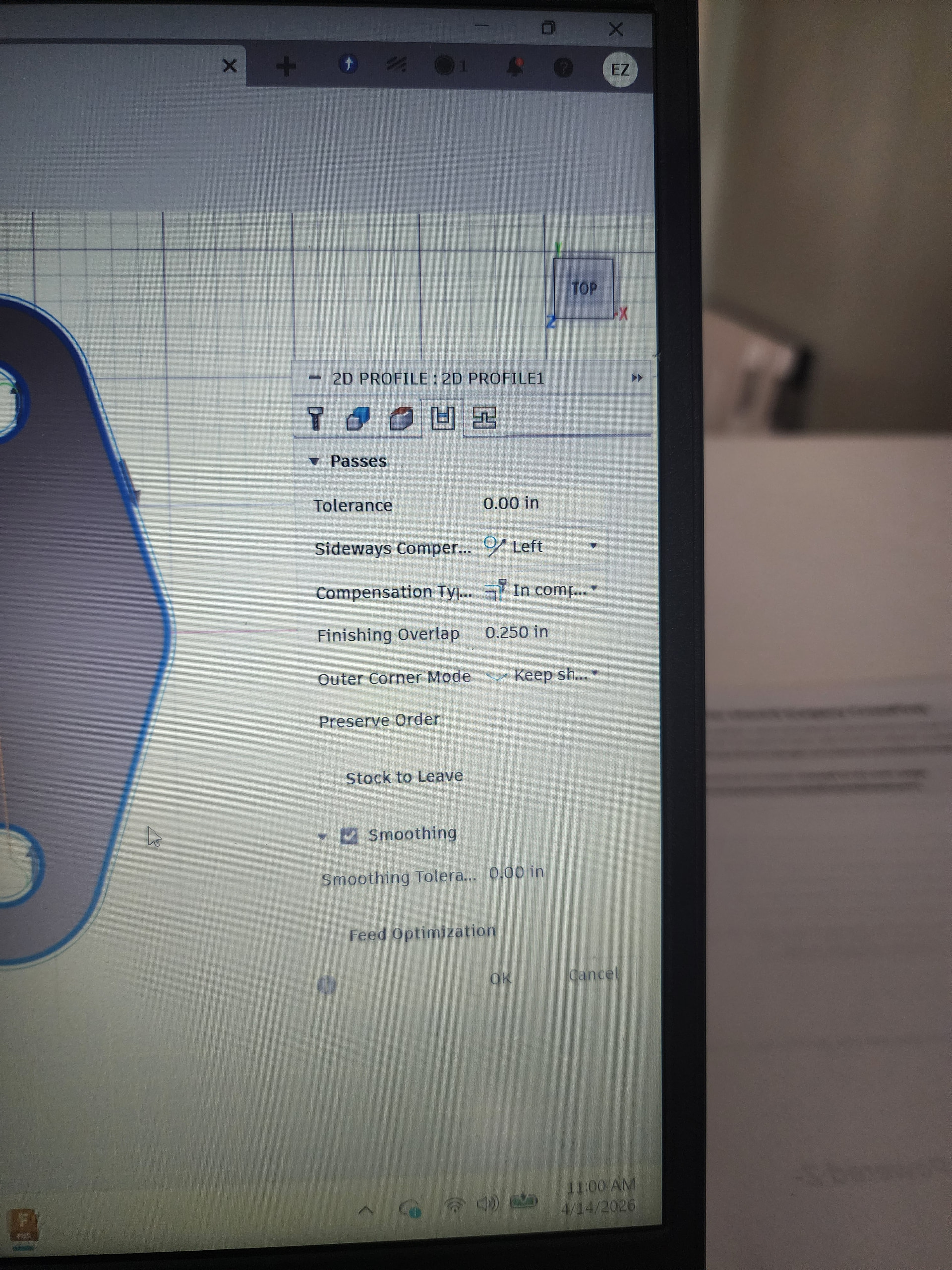
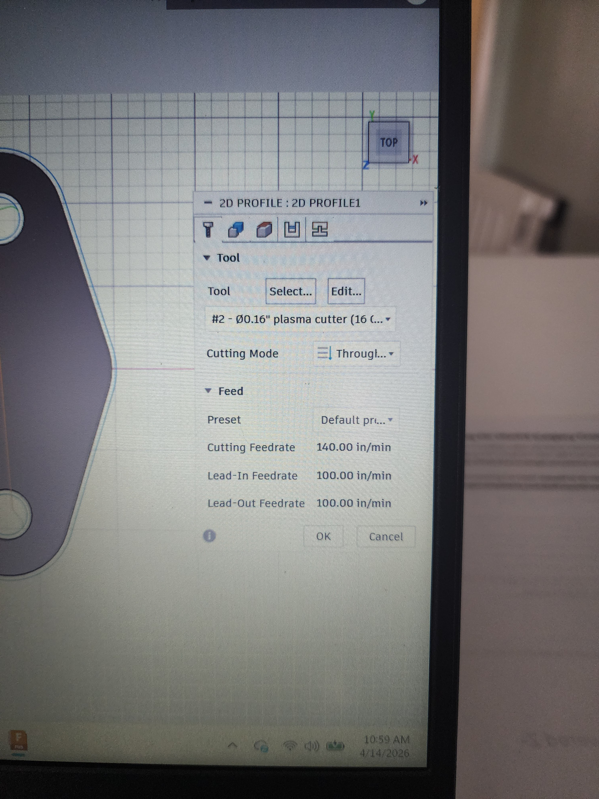
i got the pierce delay. i know where to find that but i had a couple questions about some of the other settings. where is the overcut setting in fusion? is it the finishing overlap on the passes dropdown in 2D Profile? next, where do i find the feed rate optimization? is this under the Feed in the tool dropdown or is it in Linking under leads? should i get rid of the lead in radius, and the lead out radius? and eliminate the lead out and lead in distance?
I belive I have my amps are set very low. Something like 22 amps. I can verify in a couple hours.
I see you didn’t use feed optimization you you slowed your lead in feed rate with the first menu of the 2D profile settings.
The overcut I was just using the wrong word for it’s the finishing overlap you can see it in your one screenshot there you have it set to a quarter inch.
Eliminate the lead out entirely.
I think I understand now. I will eliminate the finish overlap. Increase the pierce delay. Leave the feed rates the same. Increase the amps and eliminate the lead out completely. Do I need to adjust the lead in radius?
For now you could just eliminate the lead in radius. You could go to a straight 90° on the lead in.
The lead in radius is a more effective technique for thicker material.
There’s no real right answers in here.
The right answer is what ends up giving you the repeatable correct results with your setup.
I like to start off simple and then work up from there.
2 Likes
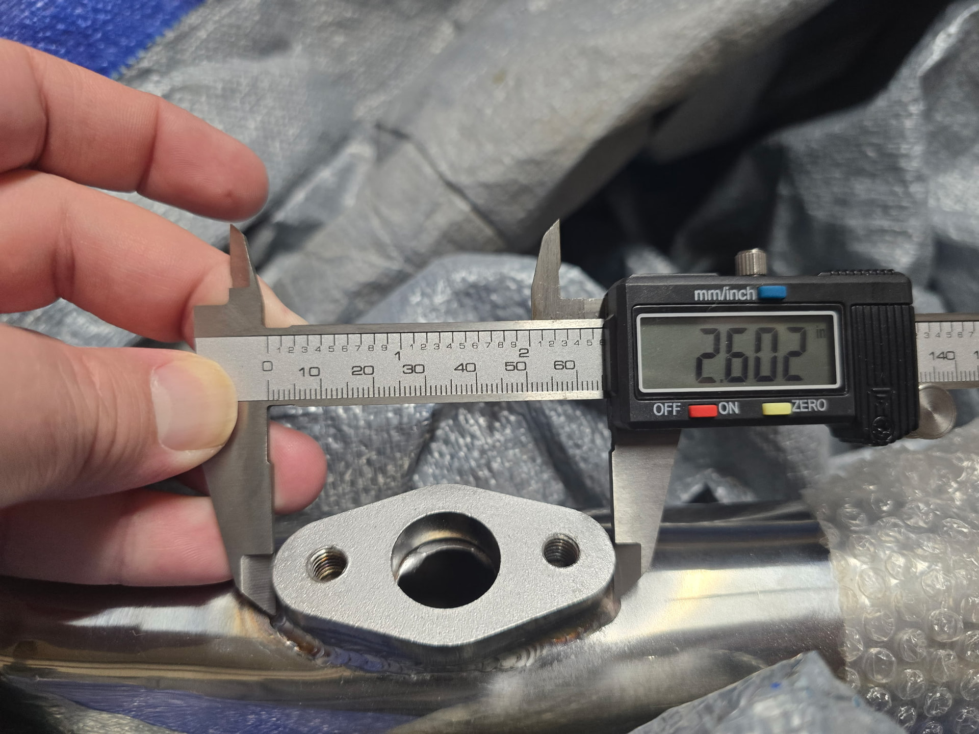
Are you making some block off plates for an engine?
Yes. I wanted to get the size right first befor I start purchasing thicker material. I have a few pieces of 18 GA so I wanted to practice on metal that didn’t cost me anything. I already spent a ton of money on everything else. Lol