Anyone fly cutting the baseplate? What was your experience?
4 Likes
Looks great! Almost hate to get that scratched up once you start making some parts. What speed/feed did you run?
What was your measured tilt/nod?
I am getting close to final surfacong pass on my fixture plate. Using a SST spindle gauge I am about .002 across 4.5 inches on X-axis and just about .004 inch across 4.5 inches on the Y-axis, think one more lower edge shim will get me to within .002 across 4.5 inches. Will hit my final shim stack tomorrow to see if I have it dialed finally to within .001 across both axis for 4.5 inches.
My squareness is with in .001 on a 2x4x6 block.
Plan on doing fly cutter for final pass after I remove about another .002 with the 1/2 inch 2 flute and a final tram check.
I plan to as long as i can get the z straight up and down. I have a tramming gauge from edge technologies for my manual mill so going to try it on the mr1
As I recall I ran the fly cutter at 1100 RPM and 10 IPM. The finish is great no issues there.
1 Like
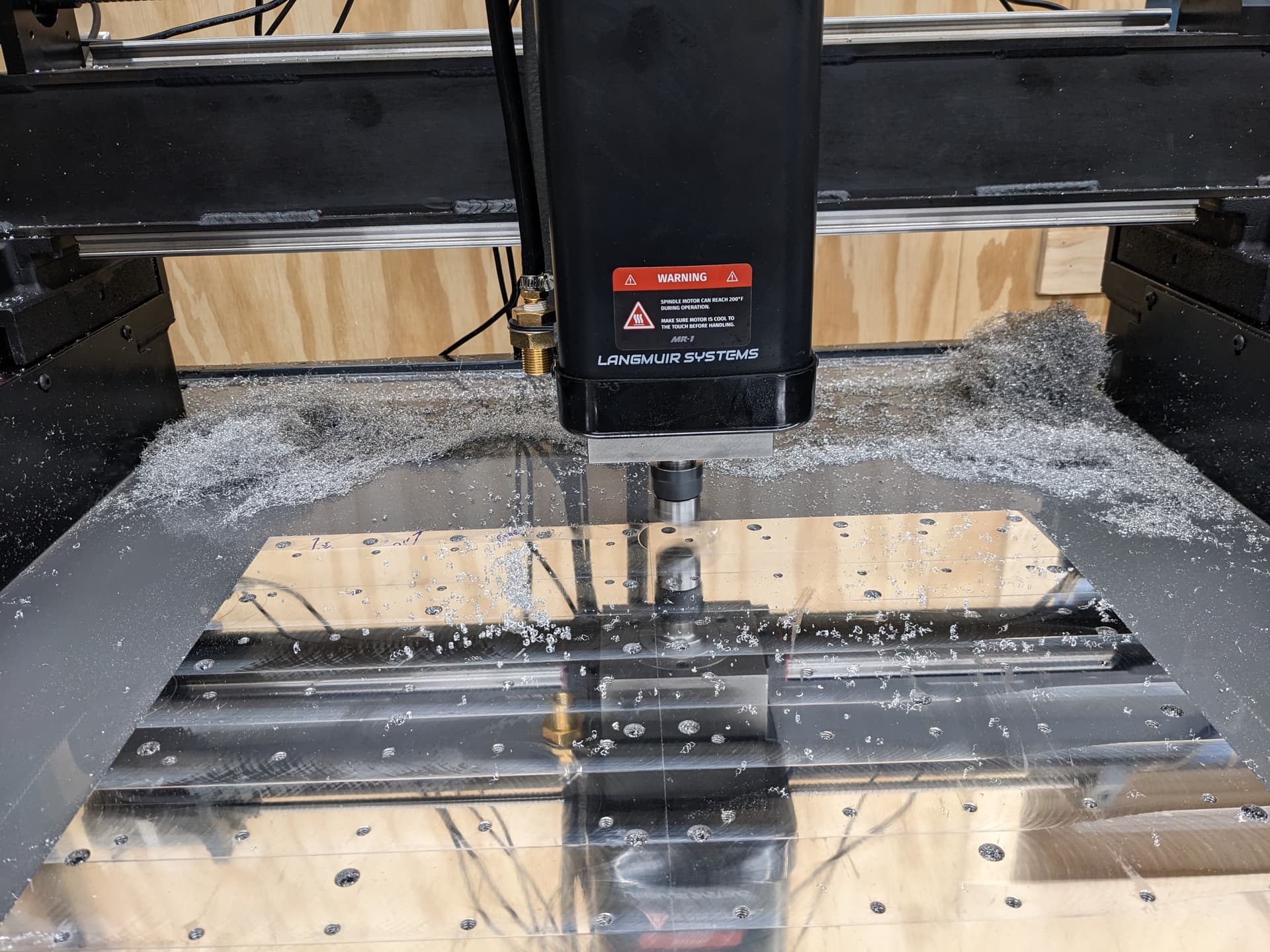
I was kind of fishing for info on results with surfacing. And I needed another day to process what I was seeing. Here’s the long version guys…
Due to a mistake on my part my mills baseplate is just a little too far to the rear and I can’t reach it all with a 1/2" endmill. So, after some roughing of the baseplate with an endmill I installed my fly cutter and set it up for an approximately 2-inch diameter cut. I roughed out that area with the fly cutter and then I started in surfacing the plate. Right away I noticed the spindle out of tram (tilted to the left) so removed the spindle, cleaned everything and reinstalled and got a much better cut. Now I have hash marks from both sides of the cutter in the X direction showing that tram is pretty darn good side to side. I was feeling good at this point. But in the Y it was still high in the front. The original shim calculations showed I should have two shims in the lower position but my cuts showed the spindle was clearly leaning back and a revalidation of the Z axis travel showed the same. If the Z travel isn’t square then there is no point trying tease the number for the actual spindle tram. At this point I’m really confused but went ahead and pulled the shims to see how it would change the cuts. At this point when I cut, I have .001 ridge between passes with the fly cutter (2-inch diameter) and doing 1.75-inch offset. I’m not sure what Langmuir considers in spec. However, the last cuts revealed something I had suspected earlier. When I do a cut in the positive X direction the cutter will cut more on one side (front vs back) then as I traverse into the 2nd baseplate it reverses and cuts deeper on the opposite side. This evening I went back and tested Z axis tram and when all the way in the +X direction I’m out just 2 thou in 5 inches but as I travel back left checking every 4-6 inches the Z axis travel goes out to better than 9 thou in 5 inches at X0.
You should get a dial test indicator or a traming setup that will hold a regular dial indicator to get this all worked out before you continue to cut more baseplate so you save as much as possible
1 Like
To be clear I’m just now getting to the point where the baseplate cleans up across the surface. It can often take .060 of stock removal to get a good cleanup on the base plate. That material is pretty rough. I do have other indicators and equipment available. I was looking for input from Langmuir or other customers on any experience with this apparent twist in the machine. As it is if I tram it will only be accurate in that location.
1 Like
the same thing happened to us when we fly cut our baseplate. The left side of the machine when cutting in the x direction (left to right per pass) the left side was perfectly smooth and once the spindle moved to the right bed plate, there was about a 0.001 to 0.0015 ridge which was odd. We checked the bed using the probe and probed each corner of the bed and over the 20 inches we had about .002 of deviation. Now, LS recommends you put the dial indicator on the side of the spindle and when we did that, it showed we had like +0.01 of Z axis deviation but when we put the test indicator in the collect using an adaptor, we had only +0.002 of deviation which was fixed to be +0.0005 over three inches which is perfect for our needs. Our coplanarity tolerance was about ~0.001-0.0005 and our tilt is ~0.001-0.0005 once again over 3 inches. SO with all of these tolerances the machine has, why the lip of the right side of the bed once the spindle passes the middle of the bed?
2 Likes
For me when I test the z axis travel for tram I get two different numbers right to left. On the right where I see minimal ridge in transition of the fly cutter (my indicator needle barely moves) its like out .004 in 5 inches. I think Langmuir says .002 in 3 inches is fine. But when I run the gantry back to the left and test I see .009 in 5 inches. Both readings were taken from a precision block places at the front center of the plate and was not moved between readings. When I sweep the table from a NOGA in the spindle I can see .002 ridges in the baseplate just the left side.
That would be caused by the upper and lower X axis linear rails not being parallel to each other. I recall looking at your X axis rail inspection tag and the reference edges are very accurate on yours. I’d recommend first double checking that the linear rails are in intimate contact with those reference edges on the x axis rail.
1 Like
Is that a typo? bit confused with the upper and lower y axis.
1 Like
There are two linear bearing rails going across the X axis to hold the Z carriage. If these two rails are not perfectly parallel (intimate contact with machined edges of the X axis carriage), then you will get different tram values across the X axis envelope.
1 Like
Yea sorry was a typo.
1 Like
Thank you Daniel,
Roger that, I will check over the X axis rails. Any reason to believe Y axis coplanarity could cause this twist? Should I check that again? Thinking I could revalidate that by placing the gauge on top of the rails?
No, Y axis coplanarity error shouldn’t materially affect the measurement.
2 Likes
The saga continues. I took the Z off and removed the gantry and the linear rails. No crud and the rails looked like they were installed correctly. Stoned surfaces again and all looked good. When I went to reinstall I noticed either the rails are not straight or my gantry machining is off because they would rock a tiny bit against the machined ledge. I put the screws in snug and used a tiny quick grip clamp to make sure the rail was snug against the machined edge on the gantry and secured the screws. I had to get new correct length screws for the lower block mine were to short. Once I got the lower block installed I had a thought. I put the NOGA arm on the lower block and sweep the upper rail. Starting at the right I read nearly zero for the first 10 inches moving left and then the number increases to +14 thou over 20 inches.
1 Like
Interesting…are you able to adjust the upper rail to make it parallel to the lower rail using the method described?
Have something similar going on with my build as well. You can see it during surfacing with the fly cutter. At some points of the table you will see the cutter leaving .001 ridge between passes that indicate the nod is tilting towards the front then on the other sode of the table it switches towards nod to the back.
Watching the tooling mark on the table is a dead give away not just by feel but by the look of the passes. Perfectly level spot has hard to define sweeps between one pass and the other.
I shimmed out my Y rails to have around .0005 of coplanar deviation. Guessing there is a slight twist in rails as they are attached to the X gantry.
This will be a complete pain in the ass to test for but it likely explains some of the issues I had in a previous thread.
1 Like
Daniel willing to try what ever, but I am not sure of the process you are suggesting. Most of my error appears to be front to back so its where the rail mates to the lip machined into the gantry. The deviation would cause the Z to tilt forward which was the error I saw when surfacing. Technically all I did was prove the two rails are not collinear. We can’t we sure which rail is out.
I didn’t mention if before but I did set the gantry up on the surface plate on top a couple of Moore blocks at the ends and checked the top and bottom machined surfaces with an indicator and it wasn’t bad at all. I couldn’t figure out a simple way to check that edge where the rail registers.