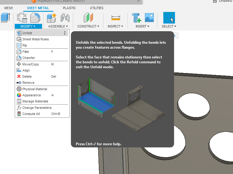
Here I am again requesting help, I am dabbling in the sheet metal tools for fusion. I have got as far as getting the flanges made and having a flat pattern and unfolding the body, now I am trying to put holes in
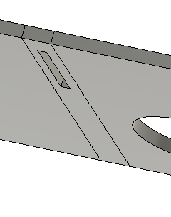
the flanges for fastening and add relief cuts to the bend centre line on the edges of the metal so I know where to line it up on my bender, I have tried making a new sketch within the flat pattern section but I can not snap to the bend lines, I have tried exporting the flat pattern as a dxf, but the results of that end up in broken lines on the design I have in the centre. Is there an easy way I can turn the flat pattern into a sketch and snap to the bend lines? The dimensions for it are 21.75" x 12" with 1" flanges, using 14g steel. I made the inside between the flanges 21.75" on purpose.
Then start a sketch and use the surface of the metal as your plane/surface. Once you make the sketch, you select the contours and extrude/cut through the metal. At times this can be a little tricky to pick the contours (until you get used to it): you may need to hide the component/body to select the contour. Once the contours are selected you will need to make the component/body visible before you can do the cut.
It does not matter what side you do the sketch (front or back), but it may matter if dimensionally the contours need to line up with something. In that case you would base that on the side that you have been aligning/dimensioning your sketch and components.
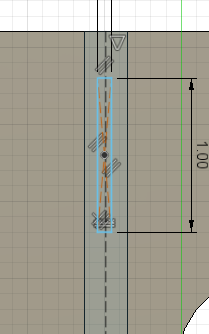
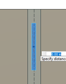
A slick way to make relief cuts in the bend:
This technique was shown by @Erock89x: Put a construction line in the center of the bend. Then use a “center rectangle” clicking on that center line. For 12 gauge I found that 0.07 to 0.09 was sufficient for a relief cut so I set that as the width of the rectangle. You can make the length whatever you see fit.
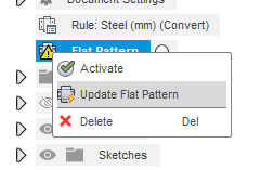
You will notice that there is an alert on your previous flat pattern anytime you make a change to your component/body. All you need to do is click “Update flat pattern.”
Edit: (scratched all of this) I am babysitting a 4 year old currently…sorry.
Jim has some good advice and methods. You could also project the sketch and use that to do what Jim is showing. Along with the center point rectangle you could also use the slot tool for bend relief. There are multiple options including the center point option. I also use the polygon tool to mark the end of the bend line.
hmm I’m not sure why you couldn’t get it to bend on the flanges, but I made the component, made the sketch at 21.75" x 12" extruded it then converted it to sheet metal and then flanges.
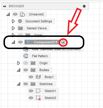
I found my error. You made it correct. This is the step you and I did not do. You must activate the component to wake it up: Just click on the component name in the browser and the black dot will appear in the black circle. This will mean that component is active and you are now working on it.
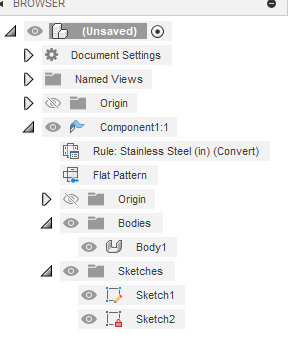
This is how it looks when it is not activated:
You had a flat panel that said steel and one that said stainless when I opened the file.
And I liked Erik’s suggestions very much. I will probably do the center-center slots from now on.
ok so I decided to start over from scratch to get this right, so I got it flattened, I can make a sketch and select the face but it only works for the main face, the bends, flanges and the tree in the middle don’t show up, how can I add these to the sketch?
I misled you. You were on the right track. Go back to your original drawing. Look at my last post.
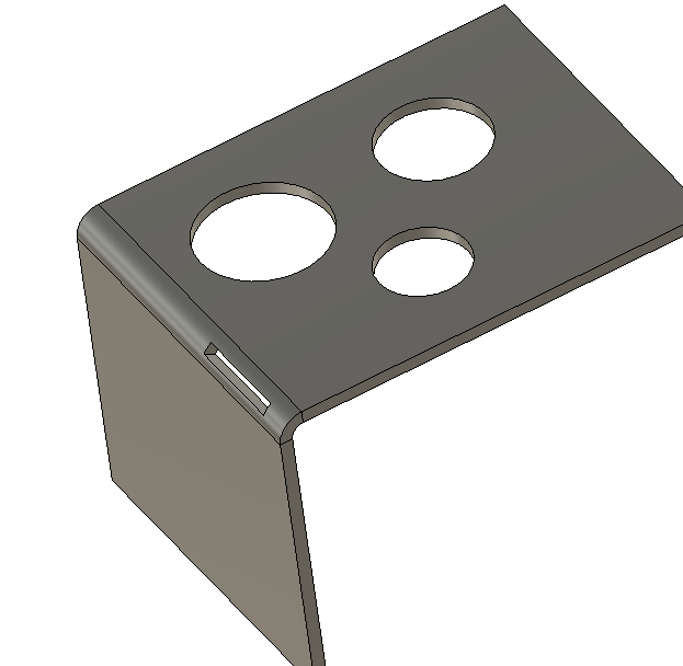
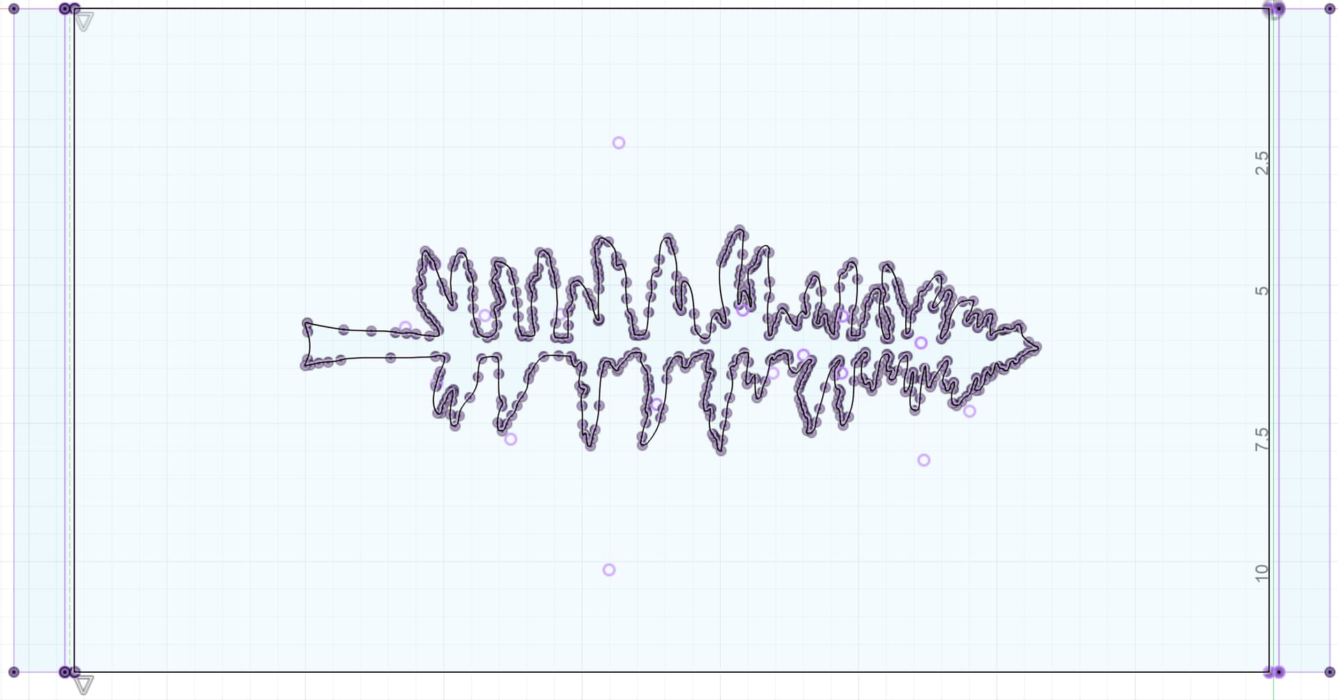
If you have lost your last file just grab it off of your first post in this topic. As soon as I selected the component from the browser list, your file worked perfectly… Tree and bends.
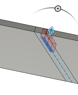
You will see that when you extrude one direction it will turn red. That means it is cutting. You will need to rotate your body so you can grab the arrow to do this. And you will not see any bend lines in the flat pattern. That is why you need to do the relief cuts or the polygon knotches like @72Pony suggested. If you still need help, let me know and either I, Don, or Erik or someone else will jump in tomorrow.
My wife just took some cold medicine and then told me I needed to watch for our granddaughter if she wakes up. She is spending the night with the grandparents!
Ok I got the relief cut out of the body and updated the flat pattern, one question though how are you cutting such thin holes? I used .07 in for the width of the relief and even set it so there isn’t a lead in/out. my kerf width is .055, should I just set the relief as a line instead of a hole and do an open chain tool path?
That is all I do to and it works for me up to 1/8th. I really haven’t seen the need to make it wider or more complicated. I don’t get too much bend but sometimes is it hard to bend, if that occurs, I cut several cuts in the same bend. As far as a concern of “strength” if too much is cut, I can always fill it in with a tig weld (usually not the case though).