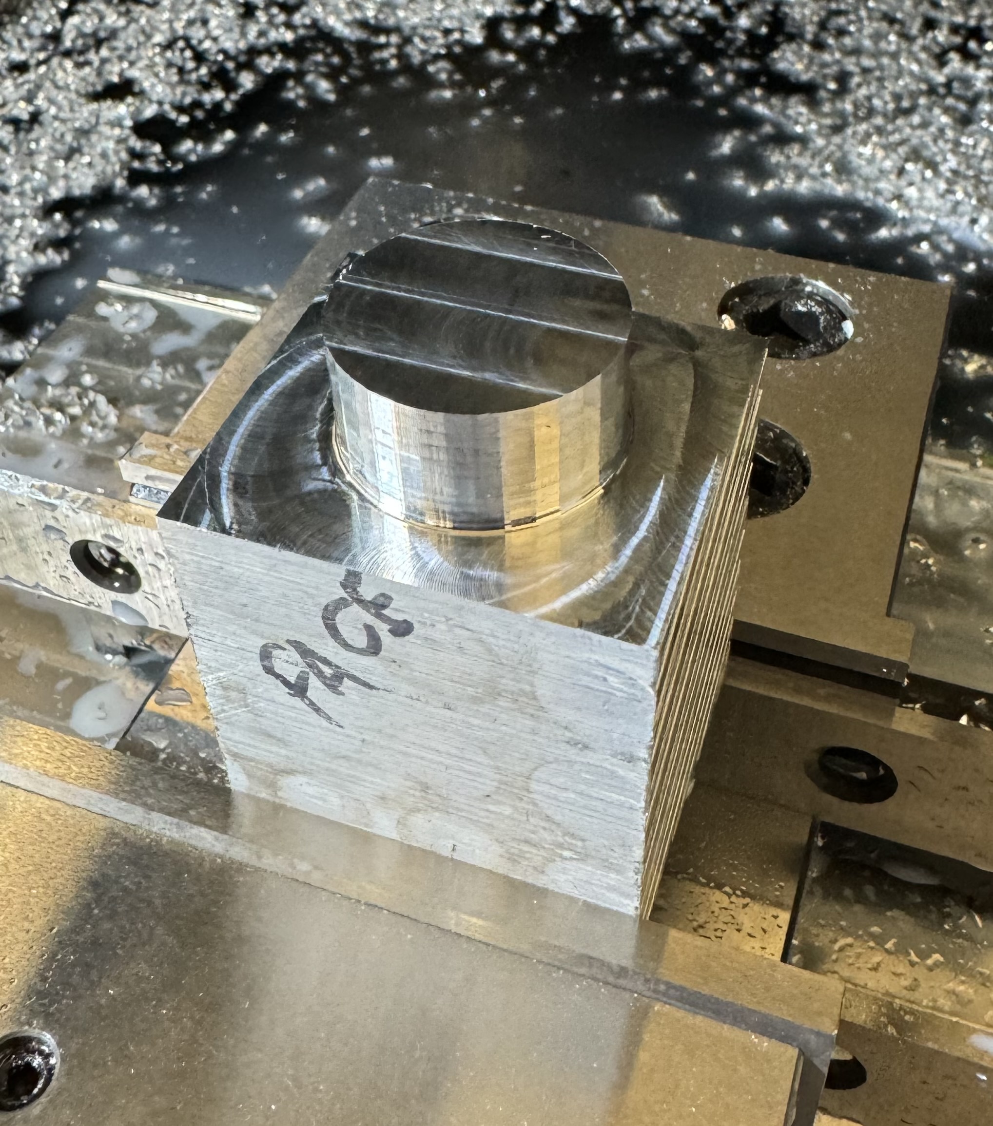
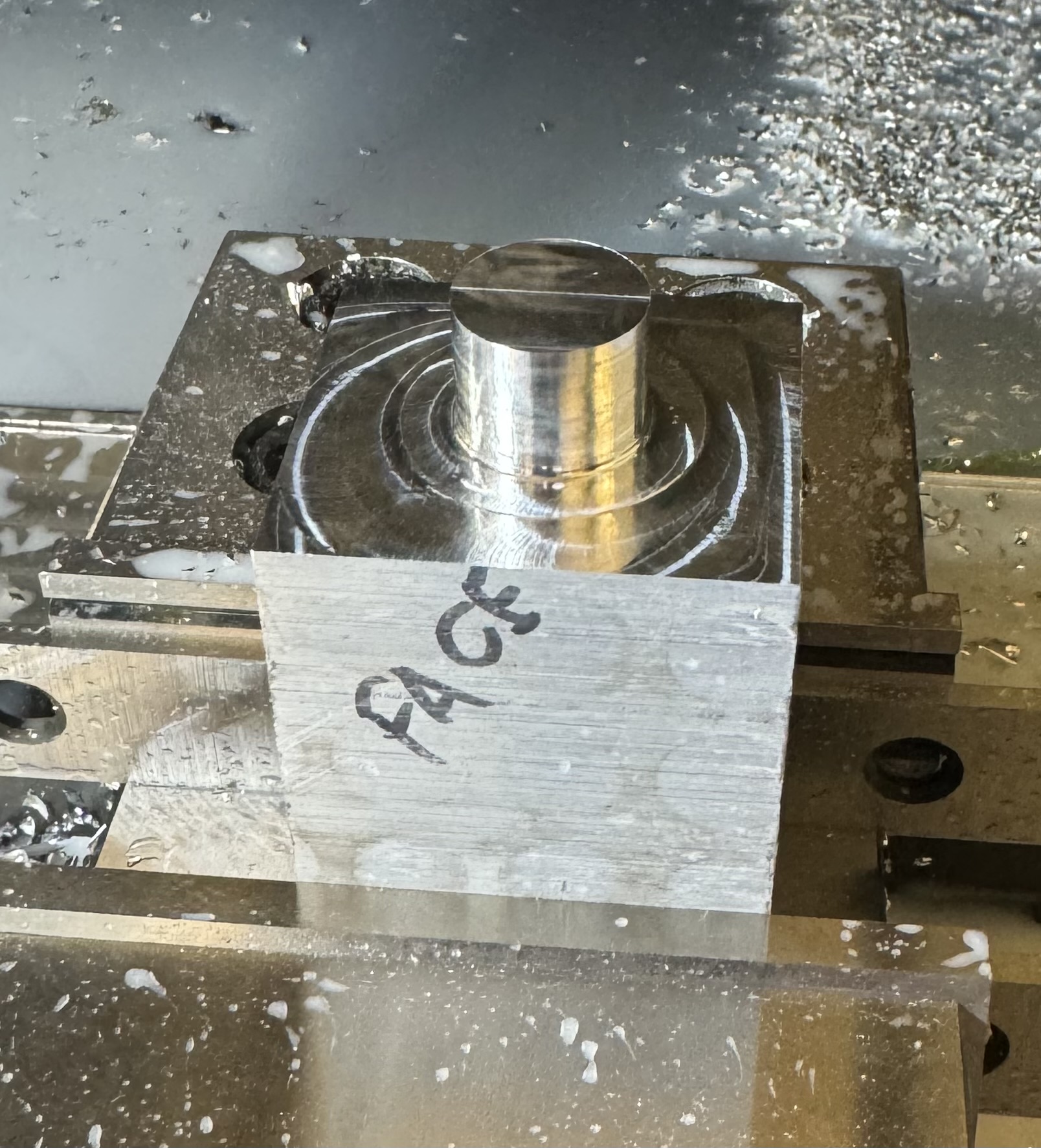
Anyone have some ideas on why I’m getting a flat face finish on round parts? Fusion setting? Machine limit? Set problem?
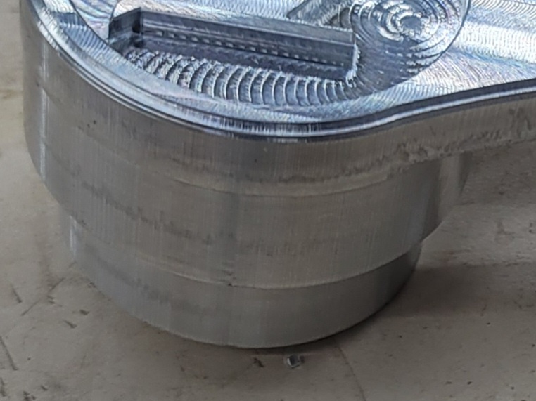
What tool path did you use to create the circular boss? I generally use an adaptive tool path to clear away the majority of the stock and then follow up with a contour tool path with tolerance set at .0004 in F360. I attached a close up of a part I made using the above tool paths. It’s not perfectly smooth but the facets are very tiny.
1 Like
Yes, it is a Fusion thing. If you look at your model in Fusion, you will see the facets. What you see is what you get. I know there is a way to change it but im not competent enough with the software to give solid advice. You can address some of it in CAD, some of it in CAM. Tightening up your tolerances to .0002 will make a diference on a tight radius. Also, some mesh settings play a big role here.
The 3d print guys run into this alot. Search “Fusion facetting” on some of the popular boards and youll see some different approaches to the problem.
Im sure someone here can be of more help, also.
1 Like
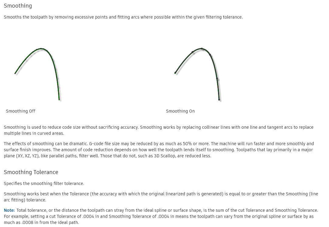
Here are more descriptions of the design/CAM options in Fusion 360 that might have some influence as TurkeyLeg suggests? You will find this in the tool path. I don’t do milling but I assume it is in the same category/tab as it is in cutting: “Passes”
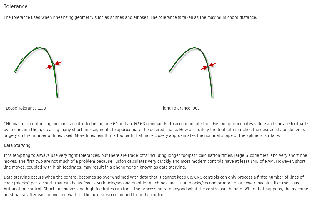
And this:
1 Like
Thank you!
I was running is in 3D adaptive clearing at the default
tolerance 0.004. Turned smoothing on, got the same results as the original.
Then I brought the tolerance down to 0.0002 and turned smoothing on to 0.0002 also. I also used 3D contour instead of 3D adaptive. Yielded great results.
5 Likes
Two changes at the same time. Wonder what the fix was 3D contour or 0.0002 tolerance? I do like to use contour over adaptive…
1 Like
Adaptive isn’t a finish strategy. Fusion 360 doesn’t do anything to create nice toolpaths with it, they always expect you to follow up with a finishing pass of some sort.