Hello. First time user. I just finished assembling my Crossfire. I have the XL extension and the Z Axis upgrades.
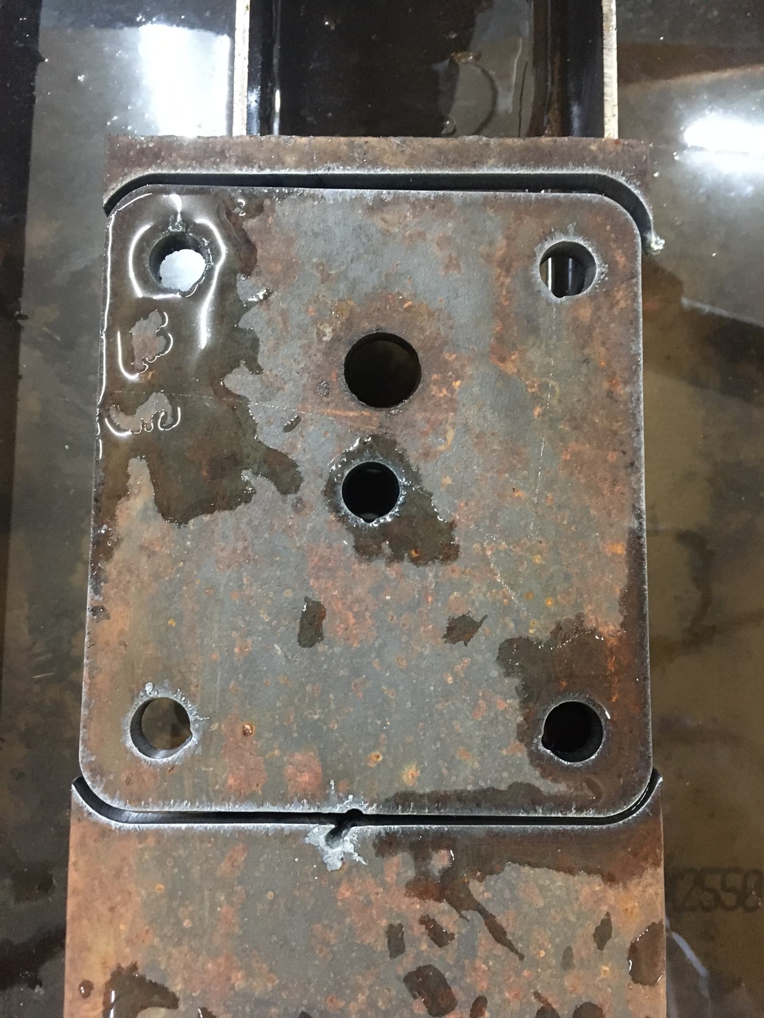
I ran the break-in program and everything functioned fine, so I proceeded to cut my first part. It’s a bracket for large casters cut from 1/4 mild steel. The Crossfire ran perfectly. The cut was smooth and everything seemed great.
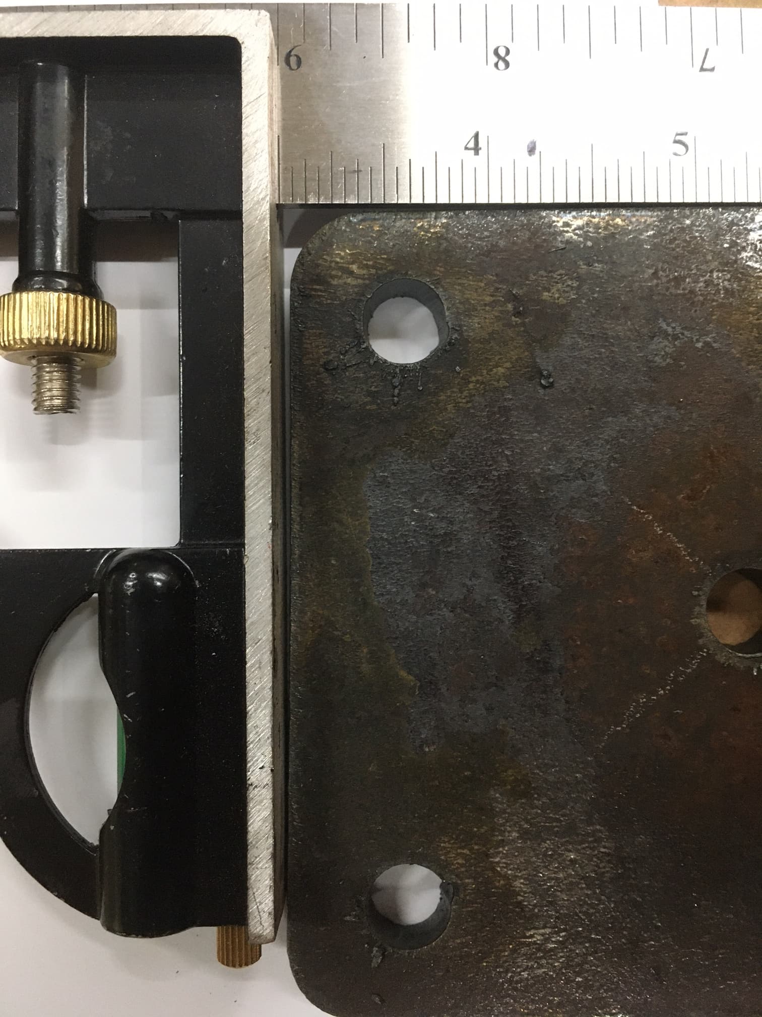
But the bracket is not square. It’s a parallelogram. I have not adjusted anything in the gantry. Is there a process for bringing into square?
On the Crossfire original and the XL, with the cantilevered arm, you may have to check and adjust the X axis alignment with the Y. A 24" framing square should be good enough to find and correct this error.
Drop the torch down to just touch a straight edge straddling the table along the Y axis, near 0,0.
Move only Y direction to the max Y and rotate the straightedge so it just touches. Clamp it down and double check to see if it moved.
Put your framing square along the Y axis with the gantry positioned midway on Y.
Now move X direction, checking alignment with the square. Ligthly loosen the cantilever arm bolts and adjust the arm position to cancel out misalignment.
You might be able to do the same thing with the Y Bearing block adjustments, but if those are already good, I wouldn’t mess with them. The other adjustment is easier IMO.
Well, you might be better equipt to use a dial test indicator to measure the distance to the edges. In my case, being a woodworker, my tools are less sophisticated
Well I pulled out the trusty framing square and laid it on the cutting deck. Then jogged the Y axis and adjust it until it was in line with the Y Axis movement.
Then jogging the X Axis I was able to see the very, very slight deviation. I loosened only the outer gantry bolt and with thumb pressure was able to correct the deviation and lock it down.
Now running the X and Y axis back and forth the torch follows the framing square perfectly.
I’ll run another cut tomorrow after work to see how well it worked, but it looks very promising.
Eyeballing your original photo, it seemed to be out of square by about 1/32 over 5" so you should have had around 1/8" or so over the full distance.
The photo may be misleading, but it appears the cut is beveled. Depending on the cause of that, you might have other issues causing a parallelogram. But, as all things CNC, take baby steps and tweak one thing at a time. Trying to do more than one adjustment at a time leads to madness. DAMHIKT!
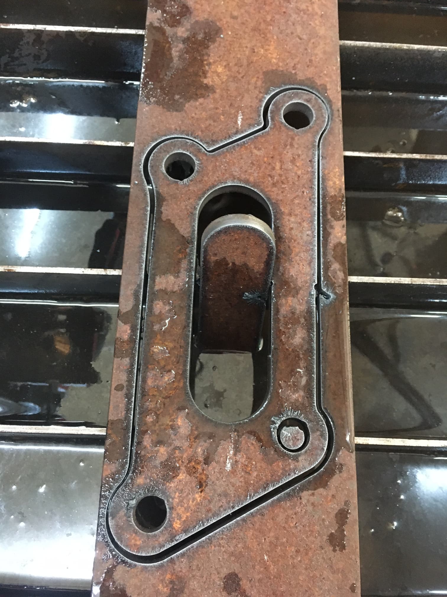
Well it worked great!! I think the slight beveling I am seeing is due to swirl direction. Still learning how to set up the cuts in F360 and I think I have some going to a left hand bias and others to a right hand bias.
Wow! Looking good!
You need some tweaking of the lead in/lead outs I don’t cut that close to the edge, but I also don’t generally cut material that thick either.