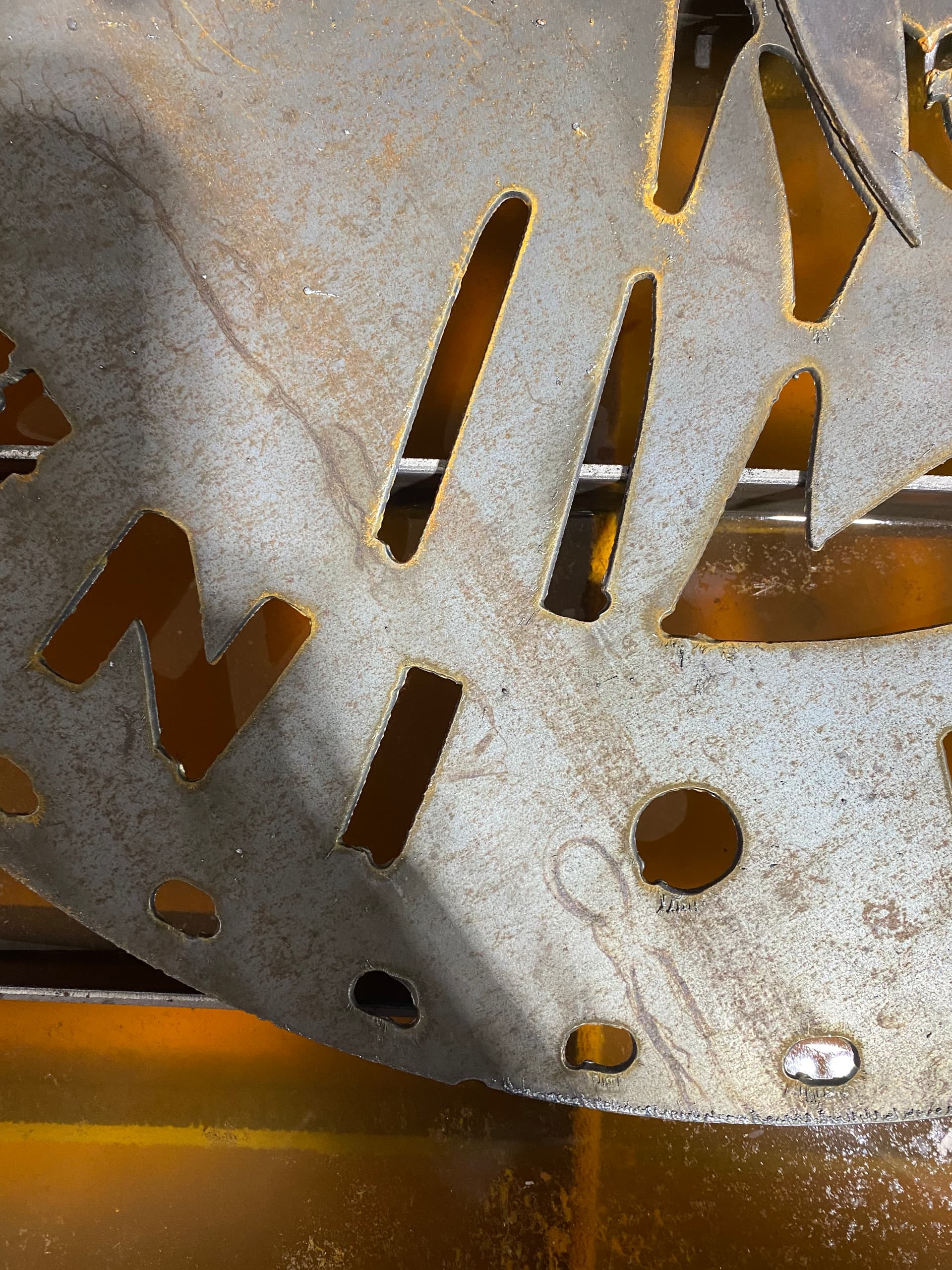
This is our first project on our XR and would greatly appreciate some helpful feedback to improve the outcome! I’ve attached some pictures to explain. Our first problem that we are working on was not having a large enough air compressor, but I don’t think that will fix the issues with the lines not coming out right. My first thought was that it was a lead in issue, but I went back and checked the 2d profile in fusion and the arrows appear to be on the correct side of the cut. Are there other settings I am missing that are causing the cuts to come out like this?
1 Like
I think your first thought is very close.
Maybe too long of a pierced delay and some leading and lead out issues.
You’ll probably have to make a few more posts before you’re allowed to post a file but when you can try to post your f3d file.
I prefer to generate my tool paths from a body not sketched geometry to avoid some of the “what side of the lines, what’s the direction of the arrow
. issues”
The other way you might be able to share your file is by creating a public link to the file. I believe in the file tab up above it has a "share "option it should be under there.
Then you can post a link instead of a file and it should let you.
Your air is one of the important variables of the whole plasma equation. you could pause and wait for the compressor to pressure up but that’s a huge pain. then the compressor is running at 100% duty cycle and hot. Then the air is hot and then it’s harder to extract moisture from. Inevitable that you’re going to eat up your time and consumables.
If you stick to short program runs you’ll probably be okay in the meantime.
And welcome to the forums.
1 Like
Here is that link, thank you for your feedback!
that is a rough file

I could not get the manufacturing space data from that link so when it lets you post the F3D file please do.
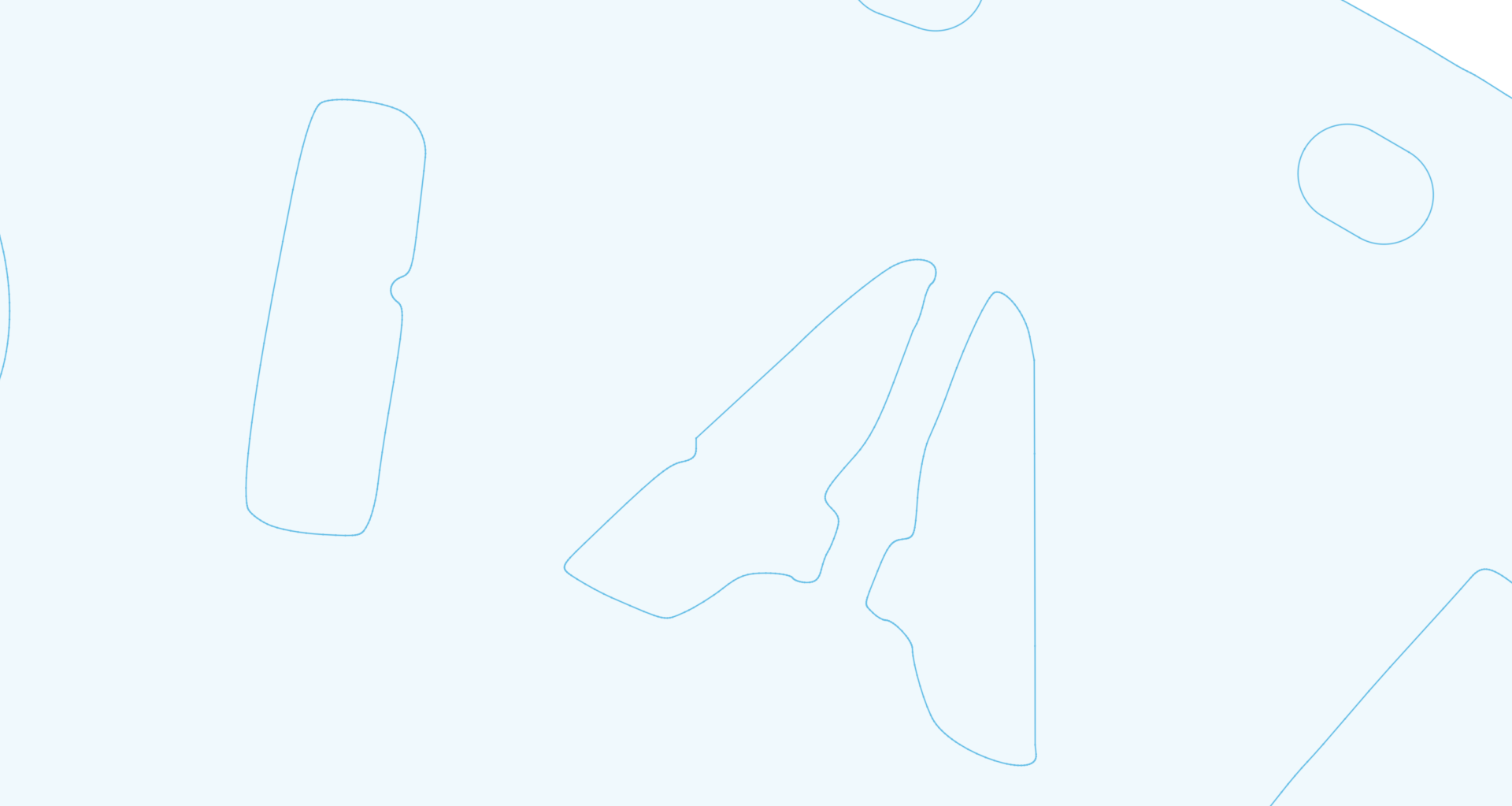
it is going to be hard to get a nice result even with optimal manufacturing parameters using this DXF.

indian motorcycle sign.dxf (588.7 KB)
I downloaded that from fire share and noticed that it wasn’t great when I got it into fusion 360, but from what I could tell the ovals that are around the border look good and all of those still have the imperfection that I thought was the lead in issue. Thanks for your help! I’ll try and upload the dxf file when I can.
Processing: Indian Sign v1.f3d.zip…
I think I am allowed to share the file now, but the f3d file is unfortunately too big to post even after compressing to a zip file.
But you’re going to have to just wait a minute for that file to fully download before you hit the reply button.
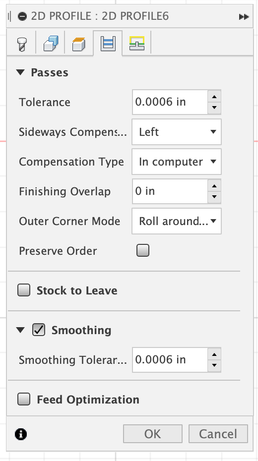
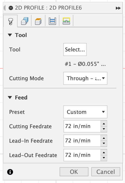
It just comes up with a pop-up box that says 4 mb is the maximum file size (mine is 4.7 mb) and then removes the file before it will finish uploading it or just stops it. If I screenshot the settings from my 2D profile, would that be helpful?
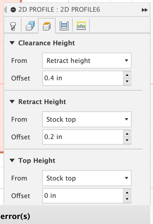
Yes you could do that also the post page the one that contains your Heights and delays

What torch and consumable pack are you using?
Change theses to start
lead in radius .03
lead in sweep angle 60 deg
lead in distance .07
your feed rates look slow but I do not know what torch and amps you are running
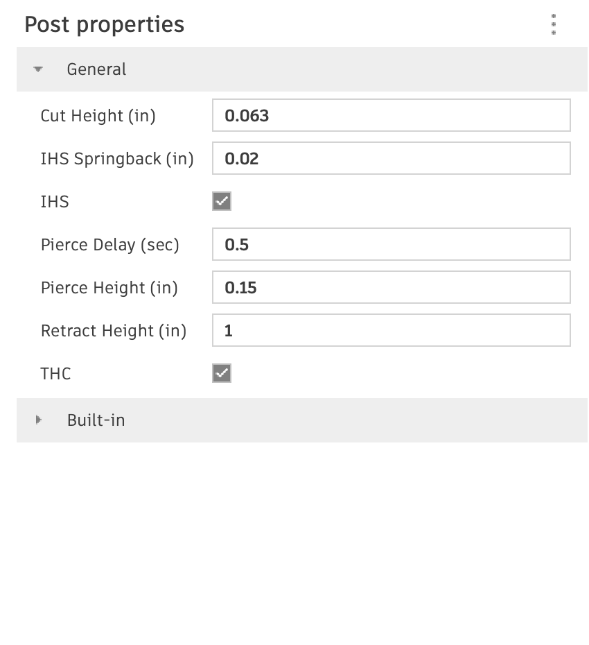
What is your
cut height
pierce height
pierce delay ?
That looks like a bitmap trace that someone made no effort to clean up. That will take a lot of work to make it into a clean cutting file.
@ds690 likely vectorized several times
I did a quick image search and run one through convertio. I am amazed at how good convertio is getting.

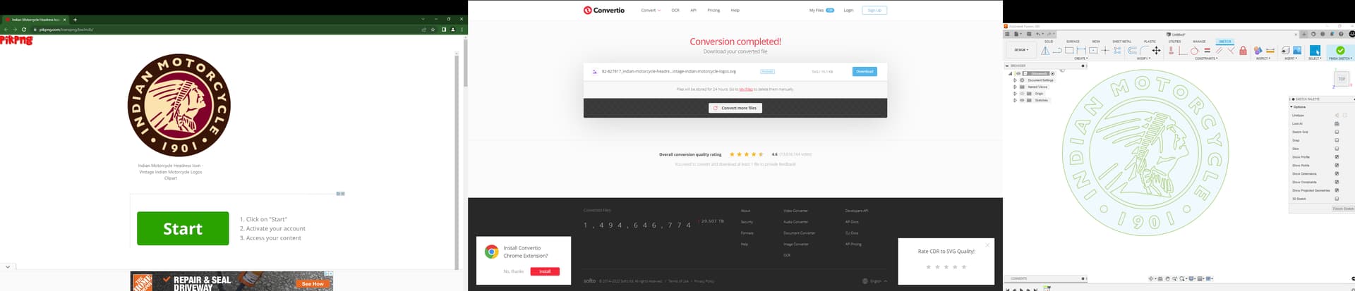

still need to be stenciled but under 2 minutes of work so far. took longer to write this post.
2 Likes

I wasn’t aware you could do that, thank you!
Click my avatar and there’s a link to some fusion 360 videos I have made.
They are pretty simplistic but I think they give a good overview of using Fusion 360 to produce files for the langmuir crossfire machines.
One of the videos goes through using convertio with images
2 Likes
I would be tempted to run it at a higher amperage and faster.
I don’t have a razor weld but there’s some cut charts on this forum site.
Just as an example I mostly use 14 gauge for signs and I run it at 45 amps at 250 in per minute. I am using a hypertherm so a little bit more power goes into the workpiece then the razor weld. I’m guessing the razor welds “45 amps” we need to run it 170 in a minute or something like that.
2 Likes
Thanks for all your replies! I finally had some time to sit down and watch your videos. I tried the settings you suggested and that seemed to fix my lead in problems on a small test project I made. I was going to try again to make the Indian sign next. Would you use the same method that you used in the flower plaque video to stencil this? Or would it be better for something like this to go at it a different way like using the spline and line tool to just trace over everything?
There’s no real spline tool infusion 360 the 3-point arc tool is typically the one I would use for tracing and it does have the function that it tries to tangent off The last arc which ends up smoothing out the geometry quite a bit.
For the Indian logo I would just run it through converter like I did above with a high resolution image or even use the SVG I posted above and then stencilify it in Fusion 360. Very similar to the flower plaque video, yes
2 Likes