I’m trying sync the table to Firecontrol. I home the torch head.
Then go all the way to the right, then all the way forward, and take note of the coordinates.
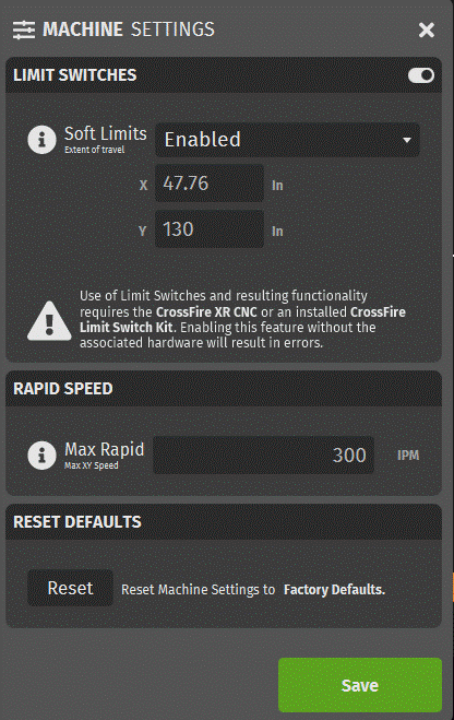
I then go into Machine settings and enter the values x =47.76 y=130 for soft limits.
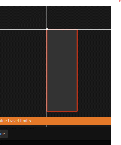
The rectangle comes up wrong for the table layout.
It should be longer left to right, not up and down.
Any help is appreciated.
Thanks
You entered a width of 47” and a height of 130” (over 11’).
Just change your Y to 33”, the correct cutting area of a Crossfire Pro.
Unless there was a specific reason for the 11’ travel distance in the Y direction - the layout shown is because you made it as such.
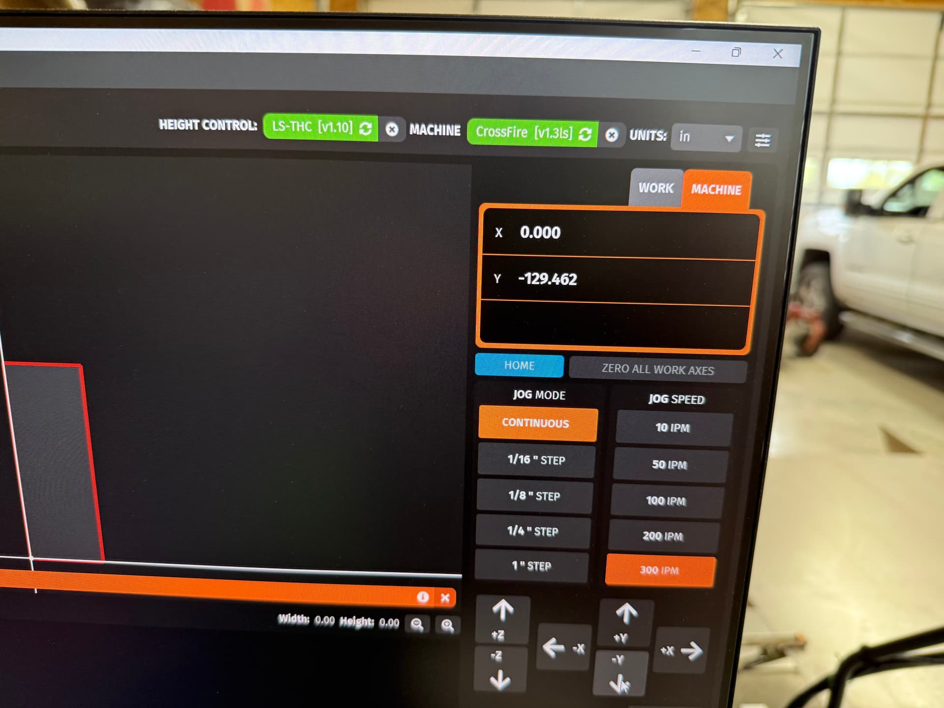
That makes sense, but I got the number by jogging the machine to that location. Why then does FireControl think I’m moving that far?
Thanks
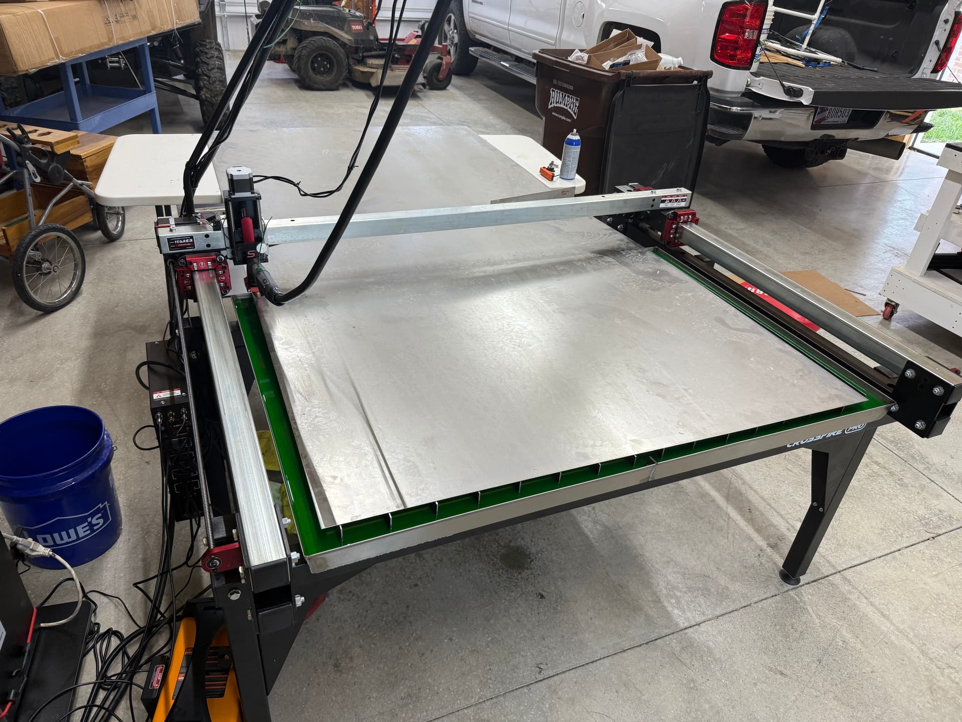
Post a picture of your table.
The “130” traveled is not possible and may show such a high value if you’ve virtually jogged the torch in Firecontrol with the table off.
You can jog indefinitely with the table off, and Firecontrol’s values for X and Y will continue as the software has no travel limit.
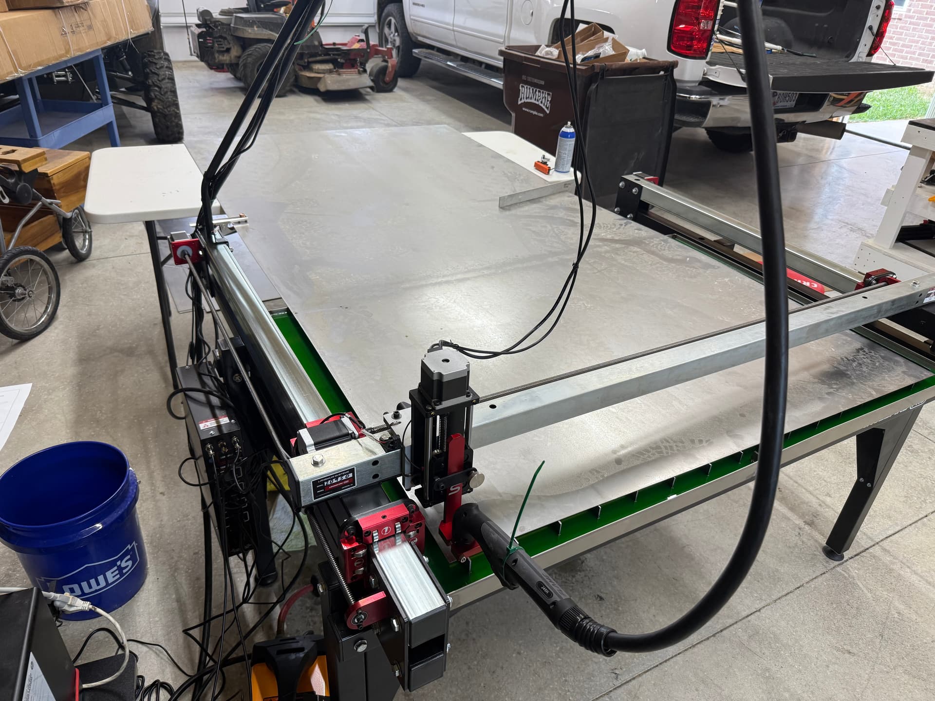
First pic is at 0,0 Then jogged to front of table.
Langmuir designated top left as 0,0?
That’s wrong on every table ever.
The standard 0,0 location is bottom left, I never knew that about limit switches. Then again I think they’re pointless on a small table.
Not a solution for your question but I’d personally remove them.
As for the incorrect travel distance, can you just open up your controller panel and take a picture of your driver’s DIP switch orientation?
It would be crazy odd for both Y axis drivers to be incorrect, but it’s the only thing that’d make sense to me.
Both of them would need to be in the incorrect position to display an incorrect number of steps in relation to physical movement. And they’d both need to match in order for both Y axis motors to jog simultaneously.
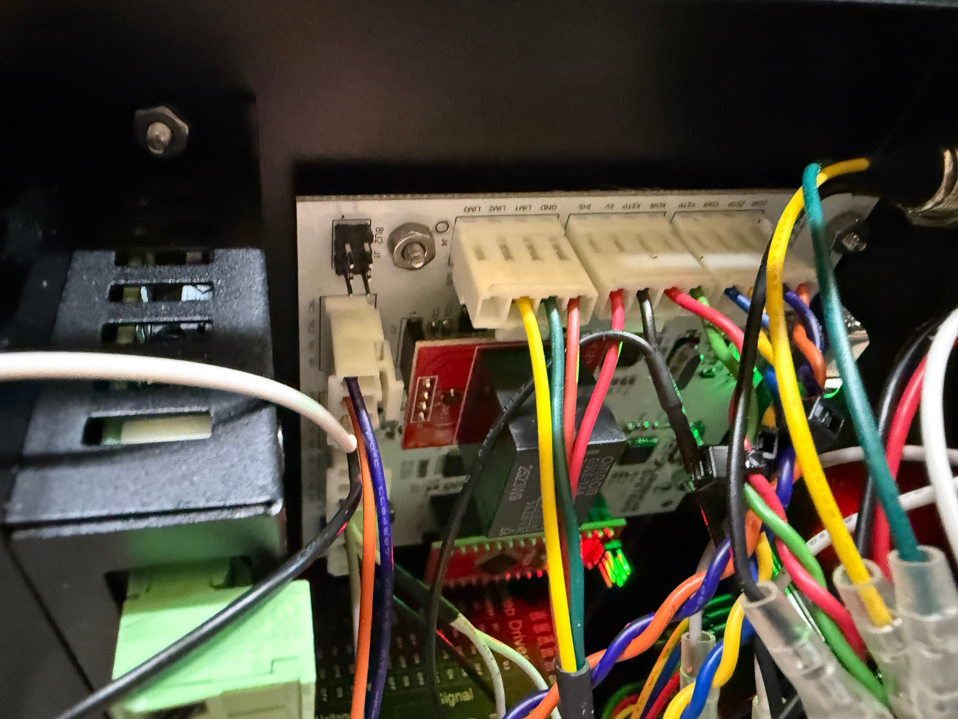
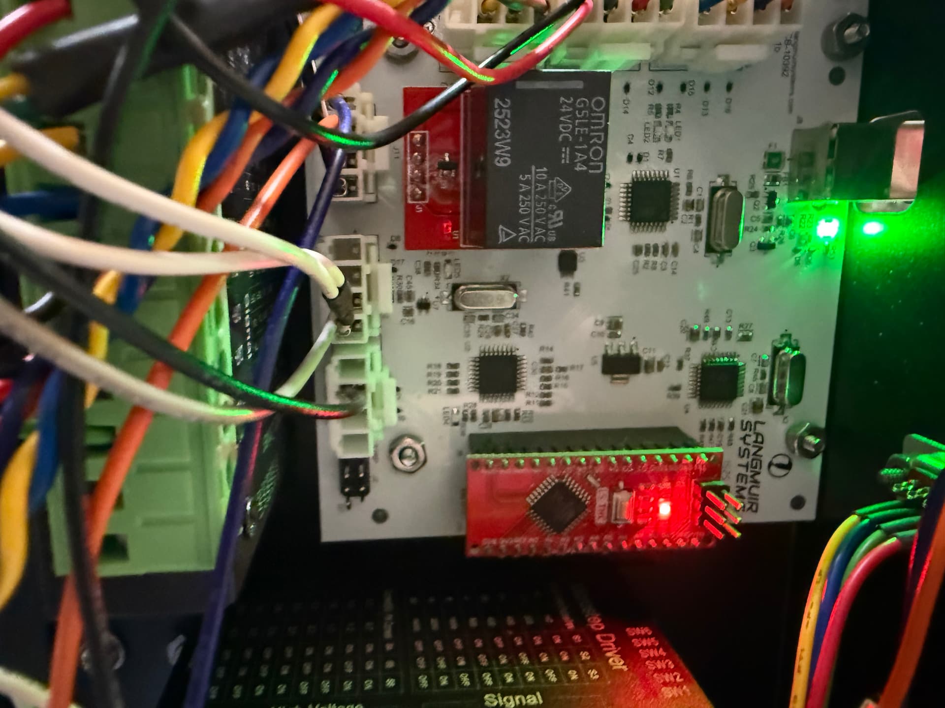
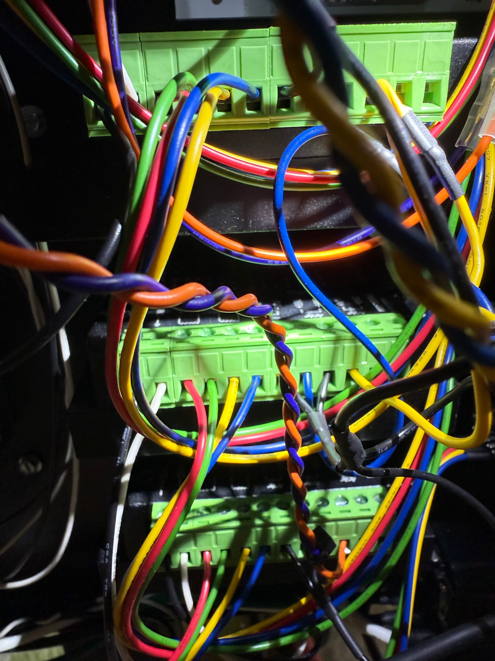
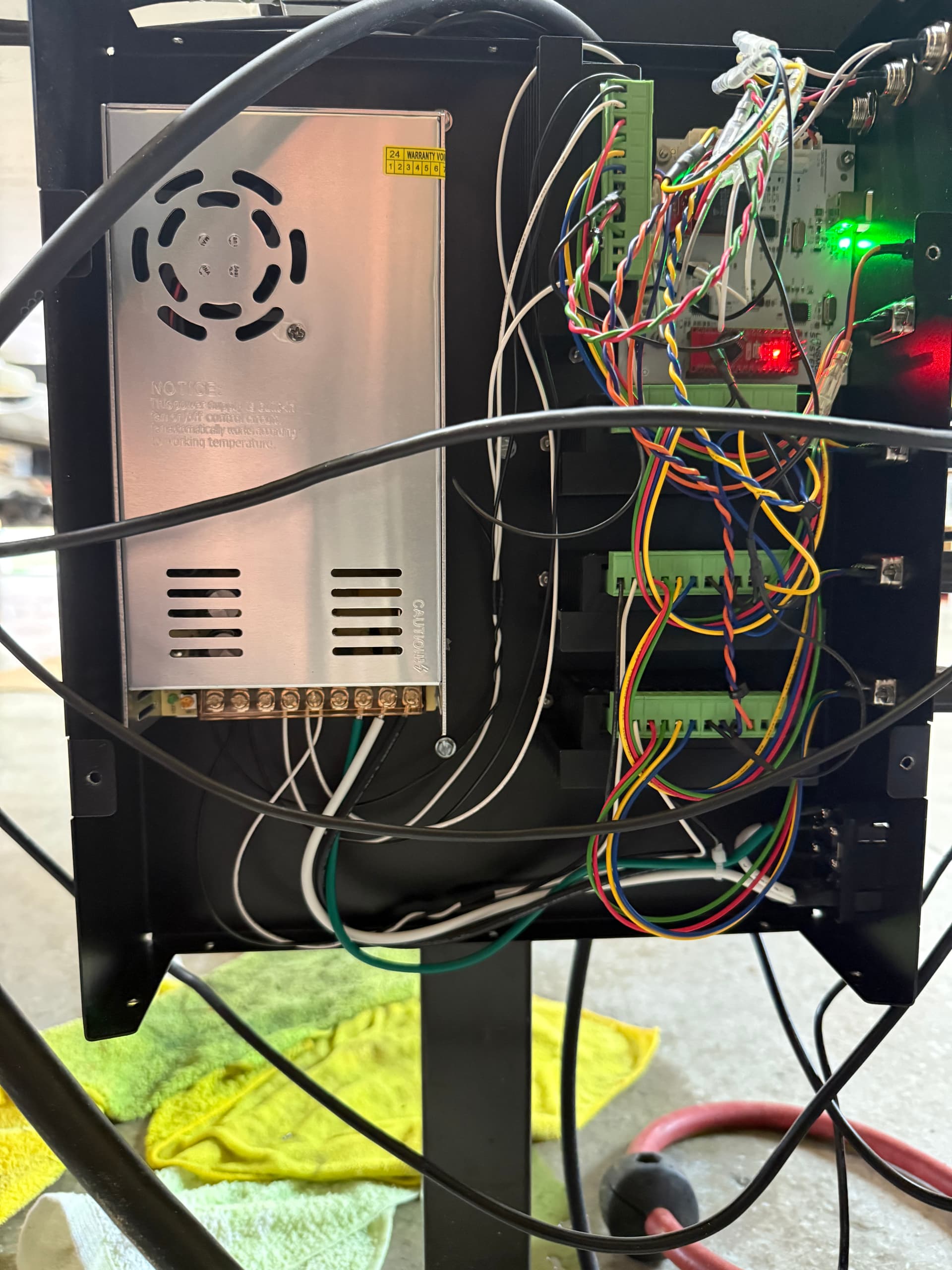
I have no idea where these dip switches are. Attached are pictures of the board.
The little black boxes that the motors connect to are your drivers.
Their dip switch orientation determines the “pulses” sent to the motors for movement.
You’ll see little white switches on the small black boxes; get a picture of them for both the X and Y.
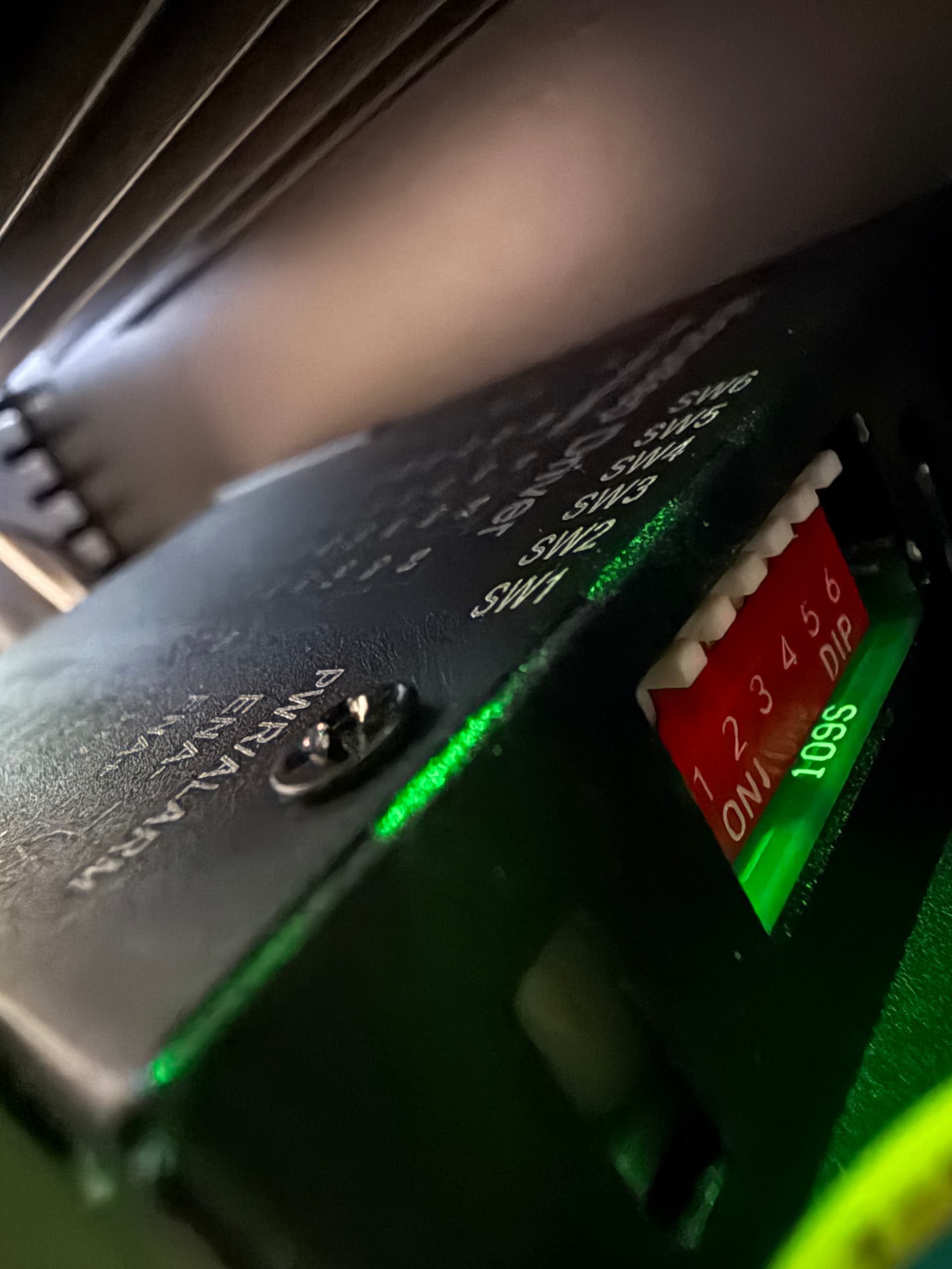
Are you talking about these?
There are white switches, with a partially red background (PCB).
They are numbered, they’re small.
Sorry not seeing the switches you are referencing. The motor wires go directly to serial ports on the front of the black box.
Bottom right of the control box, those black boxes with green terminals and wires going into them.
Those are your drivers.
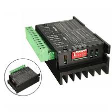
Look around close up and they will have a small layout of 4 switches.
(picture of generic driver found online)
Share the positioning of the dip switches for each driver such as
Y1 DRIVER - 1 2 3 4 (state up or down for each one)
Y2 DRIVER - 1 2 3 4
X DRIVER - 1 2 3 4
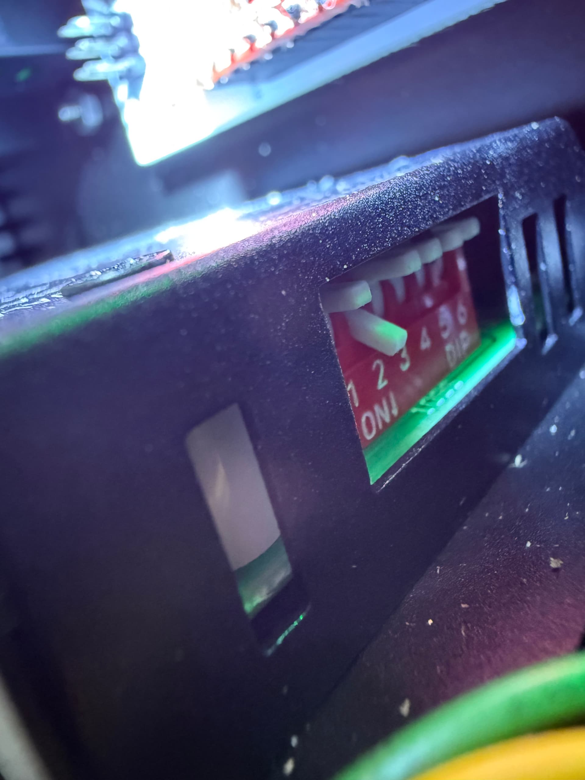
Ok, found the pesky things.
You’re not sharing the position of the dip switches and which ones are in what direction.
I say this because X and Y should both be the same, but Z may be different than the rest or not.
Just share what I suggested above.
Y2. All switches are up
Y1 only 2 is down the rest are up
X only 2 is down. The rest are up
Z only 2 is down. The rest are up
Interesting!
If your Y switches are different from one another, I would expect them to jog at different speeds causing it to bind.
If I recall correctly, the Y and X switches both have 2 in the down position.
Someone will confirm as I do not own any Langmuir tables anymore.
But again, weird for the Y’s to be different. And the Y’s are connected to the appropriate drivers as in, you didn’t mix up one of the Y’s for the X?
ds690
October 6, 2025, 5:52pm
18
All of the drivers should have the same dip switch positions. I’m pretty sure they should all be up except 2.
2 Likes
Moved y2 dip 2 to down. Now it is good. Problem solved. Thanks!
4 Likes