Lots of good feedback. Thank you for taking the time to investigate.. Here is some clarification…
Plasma has built in connector with 15:1 Div V which was passed into the Div-IN port
This was a typo by me.. it does output 50:1 by default had has adjustable dip switch resistor network to adjust output if required. THC testing confirmed the correct output.
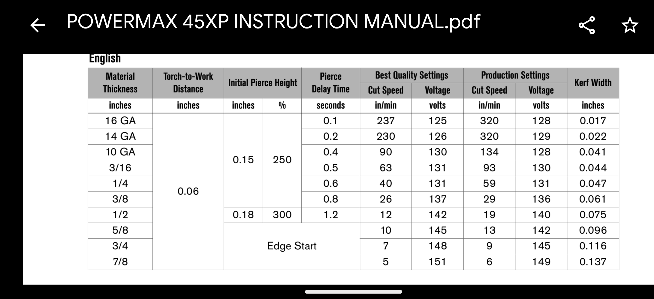
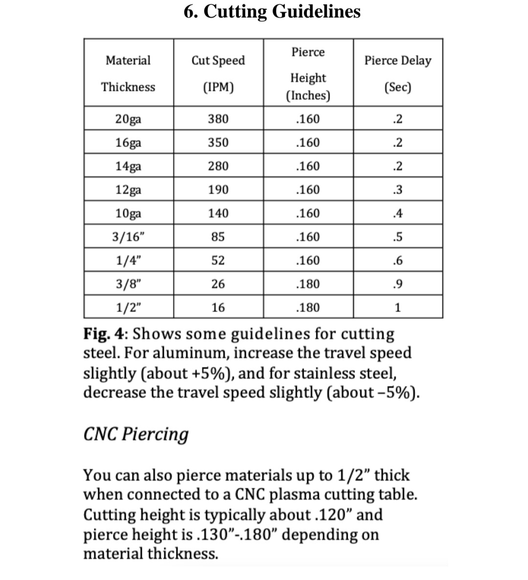
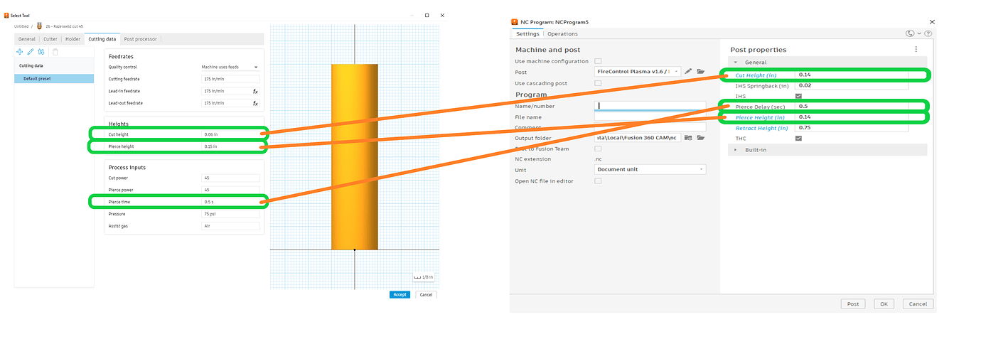
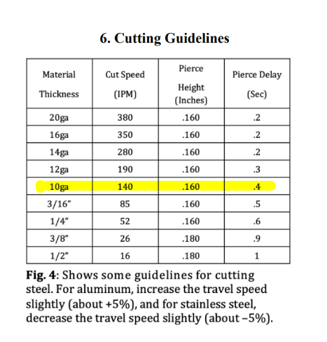
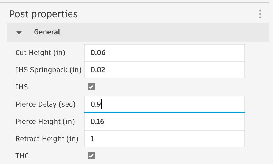
For defaults the manual the shows a pierce height of 0.16 and it also the states that the cutting height is typically 0.12 for CNC cutting
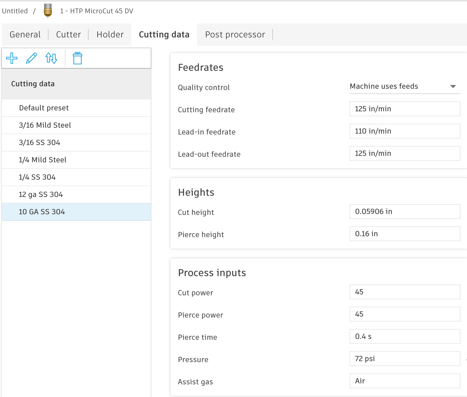
I was also confused about that language in the manual.. I called HTP and their tech advised the cutting height is 0.06 and that mention of 0.12 is not applicable. definitely confusing.
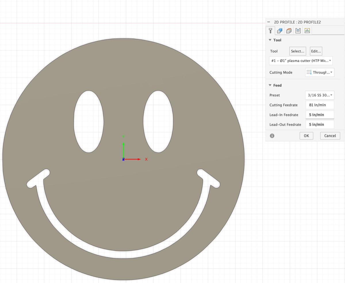
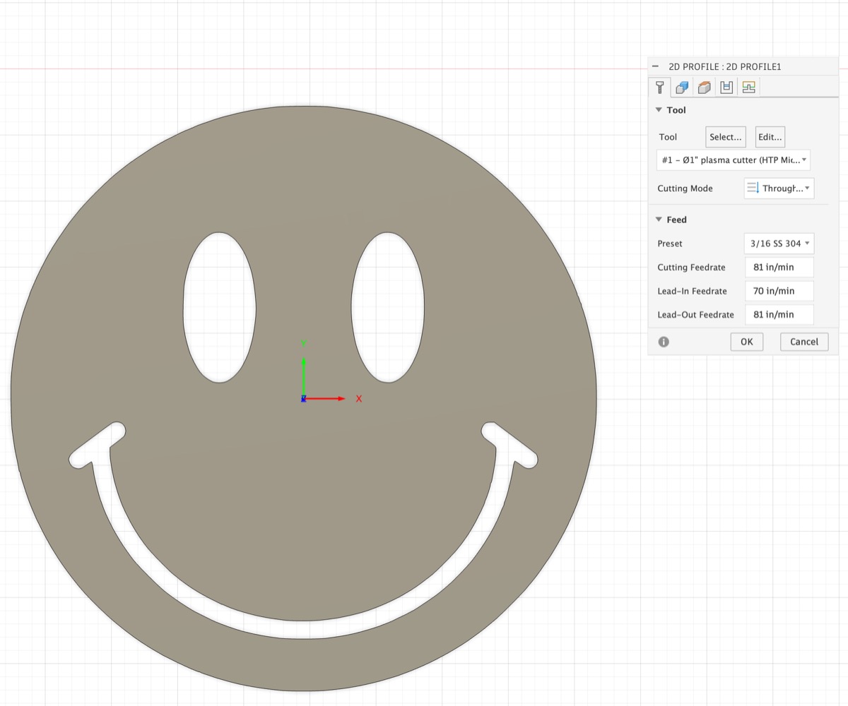
It also gives the cut speed of 52 - 5% to the 49 IPM is correct for stainless
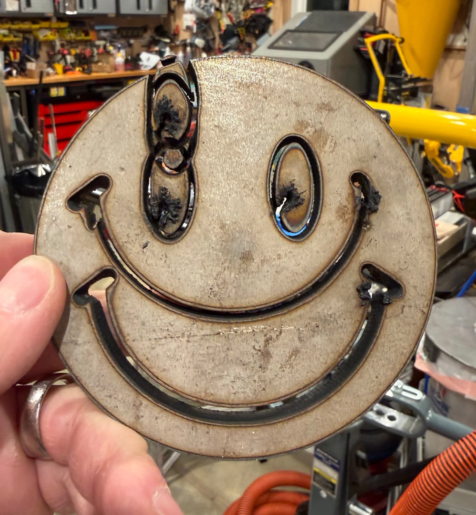
Yes, this is how I arrived at my starting speed of 49.. but clearly that is too fast for this setup. I am assuming the best way to validate is to adjust while cutting until I get clean lines without blowback above the workpiece?
the real question is how many PSI ( dynamic) do you have at the plasma while it’s running. You’re starting at 72 at the compressor but through the pipe work ,the refrigerated air dryer and the desiccant cell you’re likely going to have some pressure drop. Your unit cutting at 45 amps is looking for 4.2- 5.6Bar. (4.8 bar which is approximately 70 PSI.) my assumption would be when cutting thick stainless plate you would be to the higher end of that range. 5.6bar = 81psi .
My compressor Is set at 135 PSI with 60 gallon tank, running through 3/4 L Copper up to the 3/8” hose.. so it should be able to sustain 70+ PSI at the torch.. It is definitely blowing the water all over the place when there is not a piece present. I was more concerned about the moisture, so doubled up, running it through a refrigeration dryer and also the desiccant as backup.. so I think that Air is likely not the problem.. There is system regulated 100 PSI reaching the plasma cutter and the internal regulator is stepping it down to 72.. I believe I can adjust that if needed. The menu on the device does permit changing units to PSI, which I have done for familiarity 
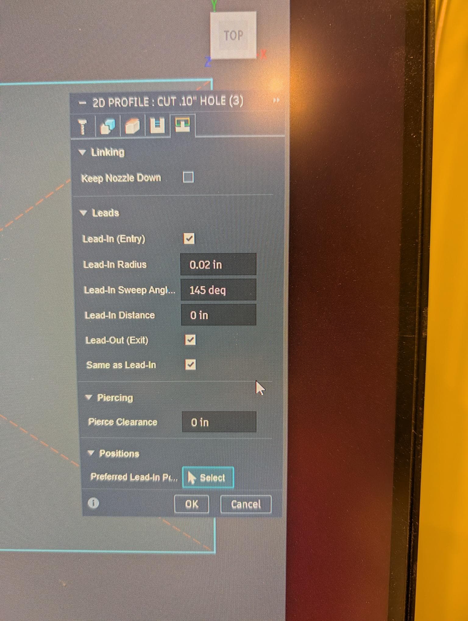
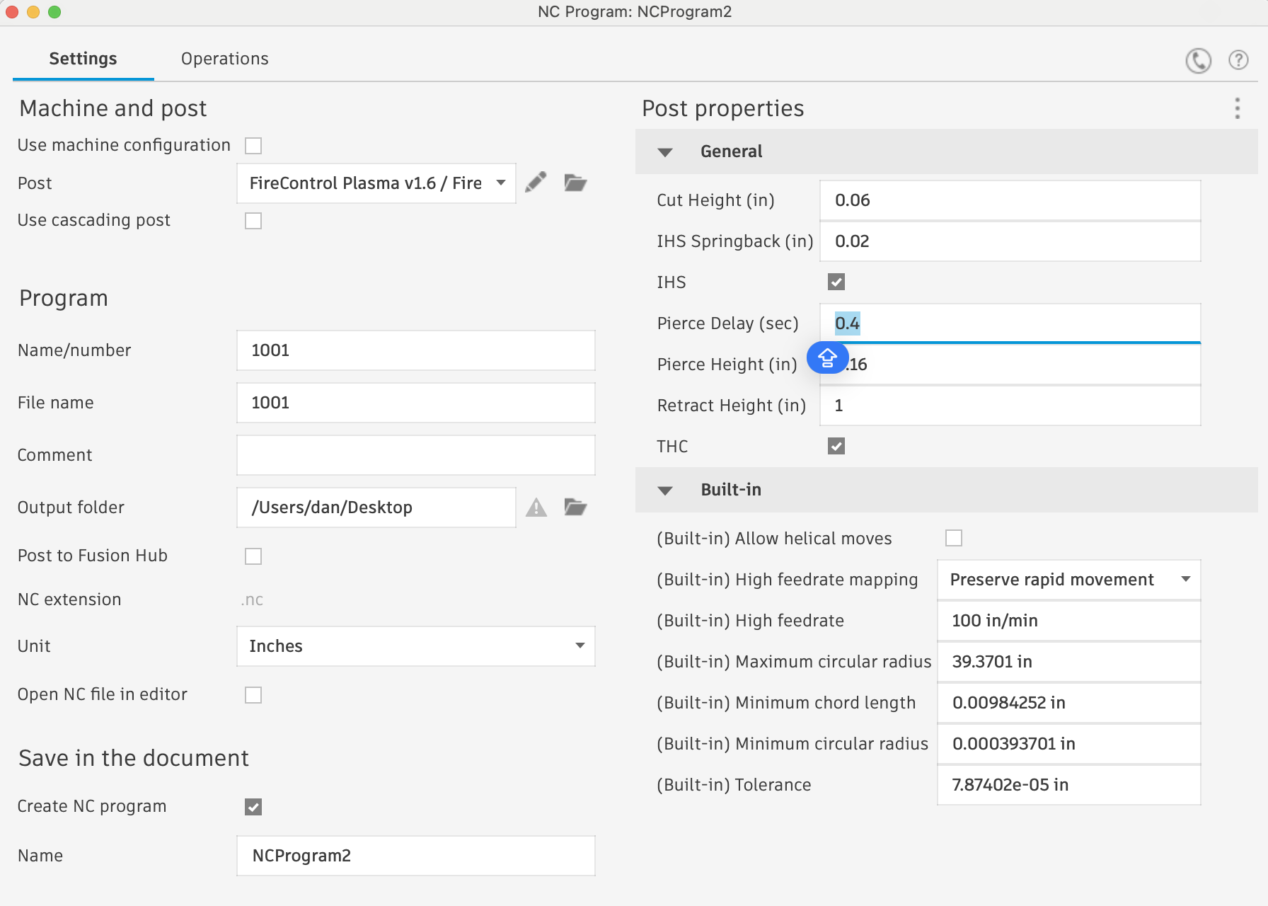
You’re running a crossfire machine so you have a built-in .5 seconds of latency on the pierce delay. So use the book Pierce delay of 0.6 and add another 0.5 for a total of 1.1 to start with.
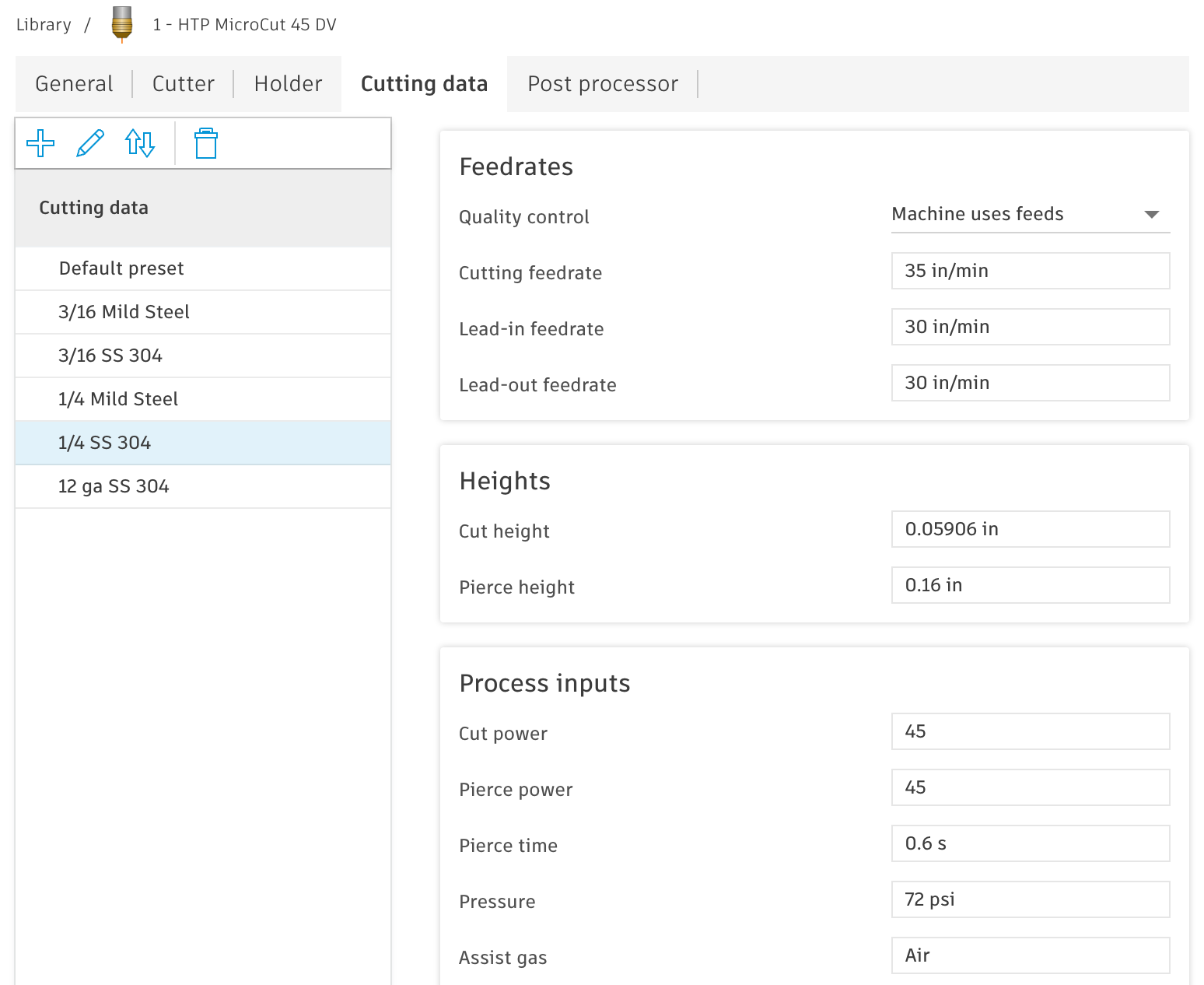
This is one, I could use some clarification on? I See a pierce delay on the fire control screen.. this value is in addition to what is programmed into fusion’s tool library settings for the material? Not an override? I just updated my tool library based on initial experience. These are latest settings.
And again get that work clamp ( often mis referred to as a ground clamp) on to the material being cut.
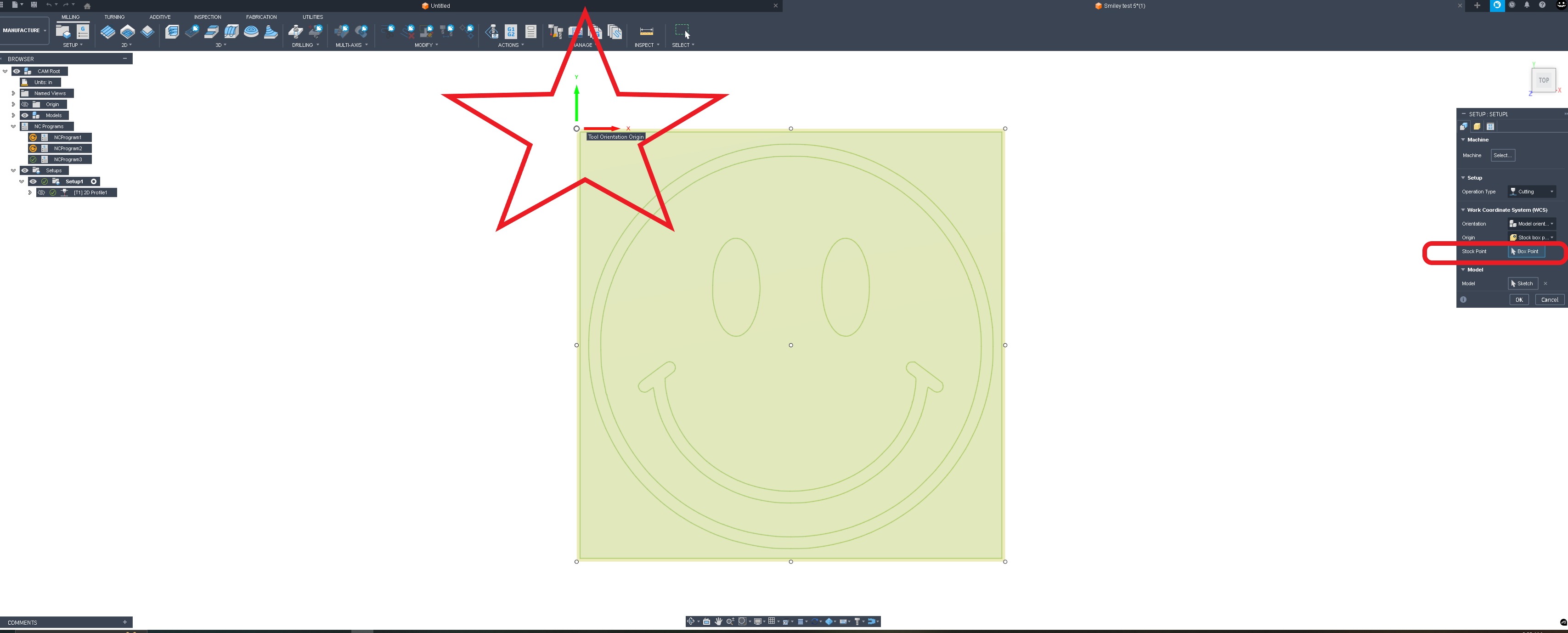
Wondering if this is one of my biggest problems.. I just had a magnetic clamp riding the edge of one of the slats. I did check conductivity with ohm meter and there was no resistance between the workpiece and the ground clamp.. but I do have multiple ground clamps with DINSE adapters so I can easily swap to a C-clamp directly on the plate. The issue with the torch popping and triggering the THC error seems familiar to manual cutting without ground connected, and just getting the pilot arc pop?
Thanks again.. will implement recommendations and see what happens.