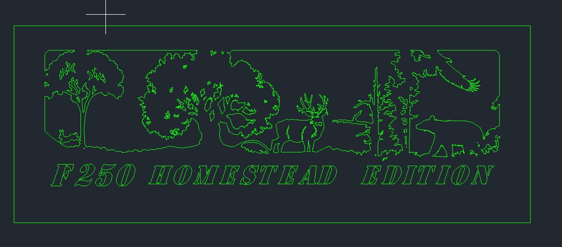
is this cut possible or is there going to be too much details lost? New to plasma, I run mills and wire edm mostly.
Some cuts would be “on line” and others “offset” I will try to upload a dxf
You’ll lose some of the small holes in the tree canopy. I usually run those kind of things with no offset so it cuts on the line without a lead-in (you won’t be able to fit one) and it’s okay aesthetically if there are the pierce holes in the remaining stock.
The kerf is about 0.06" (bigger or smaller based on material, tip, power/speed). So a cutout will have about an eighth of an inch minimum if you’re cutting inside which is part of why I make tiny holes path on the line
Spacing between letters and the small cutouts is ~.070 in spots and some of the other stuff is “close”, I know staying inside the letters will cut them out but not perfect shape due to kerf.
If kerf is ~.060 then offset will be ~.030 correct? (assume like mill/edm half of kerf is offset)
Question on kerf, can the sheetcam/control tell if over cut will happen due to kerf cutting on leading edge (like approaching a corner) and adjust tool path or will it just overcut?
I am used to programming to size in CAD and use the G41/G42 and offsets to control size, is that how this works?
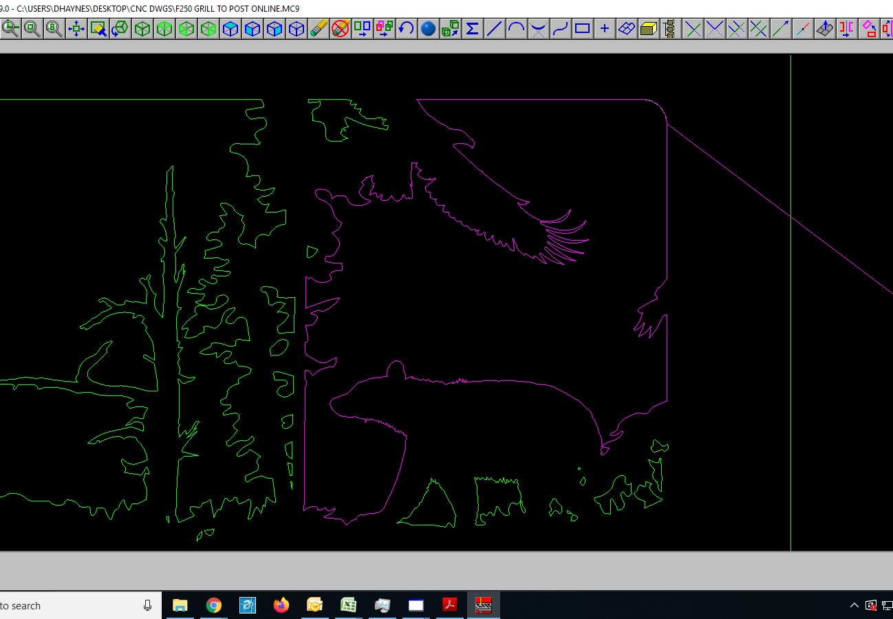
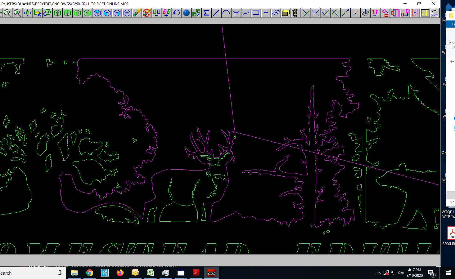
There are a significant number of breaks in the image that will drive your CAM tool nuts. I managed to join some of them with a join command in CamBam, but there are some that wouldn’t join and some that are completely open. The deer antlers for one and something in the right side with the bear that I haven’t found. Indicated by blue arrows in the attached screencap from SheetCam. These will need to be fixed before a tool like SheetCam can be run to see how bad the kerf issues are.
Umm yes & no Yes it’s a .030" offset on either side of the arc’s center. When you define the toolpath for no offset you get a cut on the line .060 wide.
However, if you do an inside or outside offset toolpath, Fusion or Sheetcam will use the tool’s kerf definition and move the line the torch will follow by half the kerf so the resulting cut should just kiss the defined line. You’ll still get a full kerf cut in the metal (like .060) but it will all be on the waste side of the defined line.
It’s just like a normal milling operation with physical mills. Just way skinnier (My laser has a kerf almost 1/10th the size of the plasma.)
One trick to see if you’re going to have a problem is to define the stroke width in your design program to be .06" and you’ll see if the objects are going to have a problem overcutting each other. That works spot on for no offset cuts.
For offset cuts, most of the design apps allow you to create duplicate offset paths so you can use that feature to define inner or outer offset paths to see if those objects would collide in metal. Just do that to a copy or Ctrl+Z (undo) after you check so you don’t end up with extra paths.
For your Sheetcam question, there is a way to define custom management of path options like slowing in corners etc. It requires a bit of scripting so it’s not typically something most people do but it’s definitely a rabbit hole you can dive into
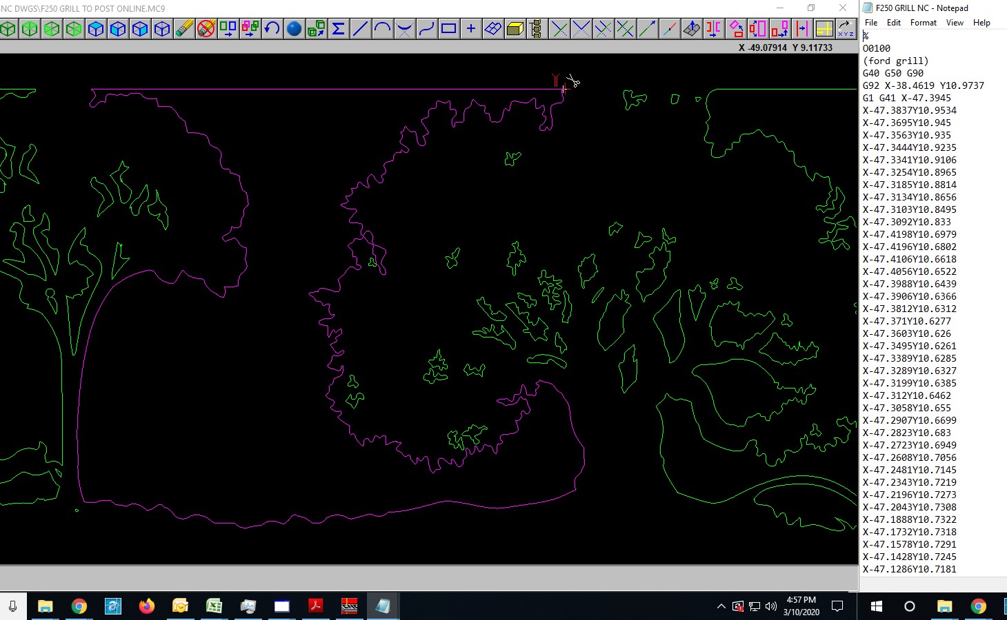
So I was able to generate Gcode (raw no correct .pst) using Mcam Wire and Mill, using no offset in Wire and .005 dia end mill in Mill, they both generate and run and seem like they would work, may try to load to edm tomorrow and see if it will run it with no alarms.
Typically at this stage, I would tweak and assume it would run on the machines (with correct .pst) Just fixed the wire.nc
Well, I had to scale it down for wire machine, it runs…now just got to learn how to fix it so sheetcam can read it and put in pierces and lead in…no way I could do that, it would drive me
Wire 2 with the Antler gap was the main issue. The second region, Wire 1, I had an operator error and hadn’t joined the two layers, so the second region never joined. There was one spot that created an overlap of two contours, but I think that was the result of my faulty join.
I didn’t think of trying a very tiny kerf in the tool setting. I just tried that and SheetCam is still complaining about “Some paths were not generated correctly. There could be a problem with the drawing.” Yeah, some help that is…
That picture/dxf is actually 3 different ones I scaled all seperately and different scaling also, as well as streched so they matched in height to my grill opening.
Then I cut them apart and copied and mirrored to make things whole(like trees), BUT it was all done in mastercam all on 1 level.
I actually made each dxf a different color as soon as I imported/merged so I could trim/delete/rotate and translate by color
So maybe mastetcam was able to make everything happy?
ETA…to add I converted from dxf to mc9, and then did work…I then coverted it to dxf to get it here.
When I open the dxf it converts back to mc9 which is what I original used.
Maybe sheetcam can’t convert it exactly the same?
Interesting
Eeek! file conversions are always potentially fraught with error. Especially when DXF is involved because that’s a “lowest common denominator” format. It’s an old format (minimally updated over time) that helps provide essentially a universal standard. But it was never designed to handle some of the complexity and advanced capabilities of the tools today. SVG is like a successor to that where it was designed to be a pretty universal standard format but long after DXF so it’s got more capabilities and it continues to be extended and developed.
It’s worth either seeing if your current toolset can work with SVG files or learning one that can.
are you able to design in that and export it to your other software for tool path or are you using something else?
I design in Vinylmaster pro, export as dxf then import to sheetcam and have had very good luck.
Normally I would use inkscape and then import it to the cut program and I can make changes there also such as nesting, scaling ( That computer and plotter are in the basement packed up because of a long term reno project lol, need to set it back up so I can make some glasses next month)
I haven’t tried that before, when I get it set back up I can def. try, most designing ie drawing is done in mc9. I am learning autocad some (I used it to scale the dxf’s I imported into mc9)
I have never had to design art before, normally it is copying stock dxf and eps
Probably 20 pcs of 1/4-20 stand offs and SS bhcs, noise?
7.3 , 5inch exhaust and the turbo acts as the muffler
Not to mention the tires and bed, noise is of little concern.
It is my go to hell truck, if they dont like it they can go to hell
I built a dump bed, still needs the springs put in, if it ever stops raining.
Bad picture