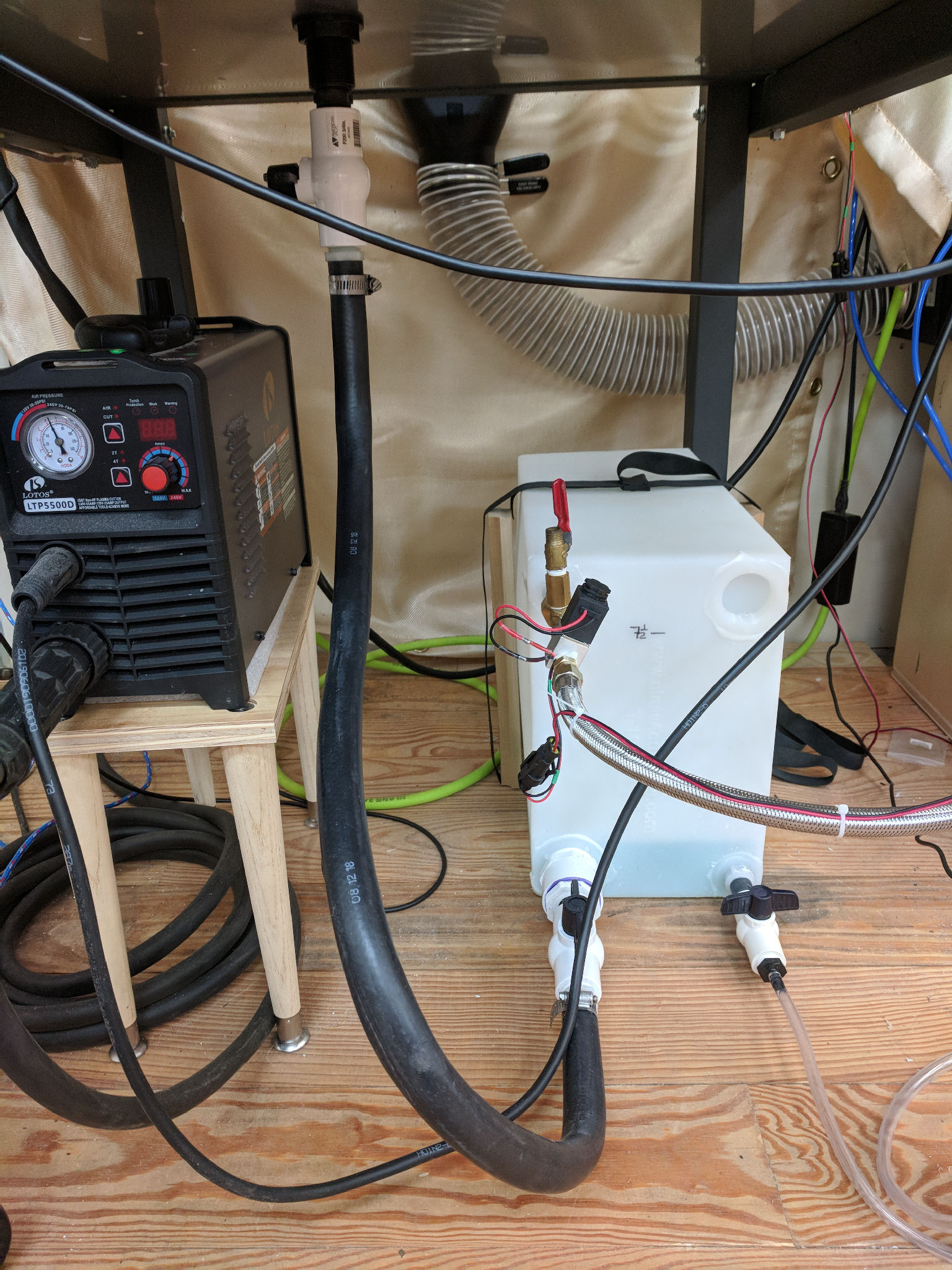
Inspired by this thread, I’ve added a water storage tank for my water table, plumbed for compressed air to refill the tank and a simple manual operation to drain the tank. With this new setup I now drain the tank after every use and refill when I want to do a run. Refill time takes 63 seconds (for CrossFire water table, not your honking big ocean you have with the Pro!) and drain is mostly done after 2 minutes, but the last little bit takes a while. Not that I care on drain, it’s just open the valve and walk away…
I’ve coupled a float switch with the refill so now I just flip a switch, it fills, and stops filling when the float switch triggers. Easy peasy and let’s me do other prep while it’s filling.
Here are the key photos, let me know if you want deets…
Tank View:
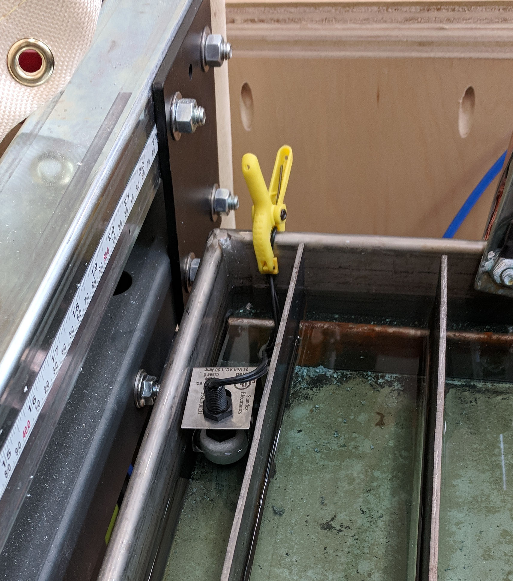
Float Switch:
Pressure Regulator and Flood Switch:
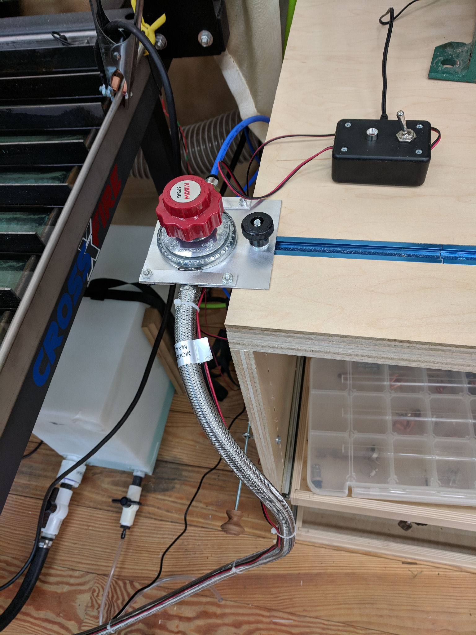
The pressure regulator is a modified “Medium Pressure” Propane regulator (5PSIG) so I have fine control on the tank pressure and neither blow up the tank or wait forever for it to refill. The LED on the Flood control tells me when the solenoid is activated.