Just remember, most of us started out in somewhat a similar manner. There are lots of pieces of information coming at you and one wrong move and you waste potentially hundreds of dollars of metal.
That is why many of us are here to help. We remember the pain, angst and frustration. On the other side is pure exhilaration.
I am seriously looking forward to what your students develop! I think it’s great that they are learning this skill and can’t wait to see what their youthful imaginations produce! Making something with your own hands and ideas is a joy every person should experience.
One thing you could try to verify dimensions, do a dry run with a sharpie taped to the torch (Z axis does not move on dry run), and a piece of cardboard taped down to the plate. It is a quick and dirty way to see the cut lines and you can get some fairly close measurements.
Does your school have a 3d printer? Task a student with a design build of a spring loaded sharpie holder that is the same dia. as the torch. Then you can turn off the THC and run the program and have your cut lines without the rapid moves to pierce points.
My student has definitely had pain, angst, frustration, and exhilaration! He is back to the frustration stage. We do have a 3D printer, but he was feeling confident about the designs, so we didn’t do the sharpie test and starting cutting metal. We still have an issue, so I thought I’d come back with photos and files, and see if someone could help!
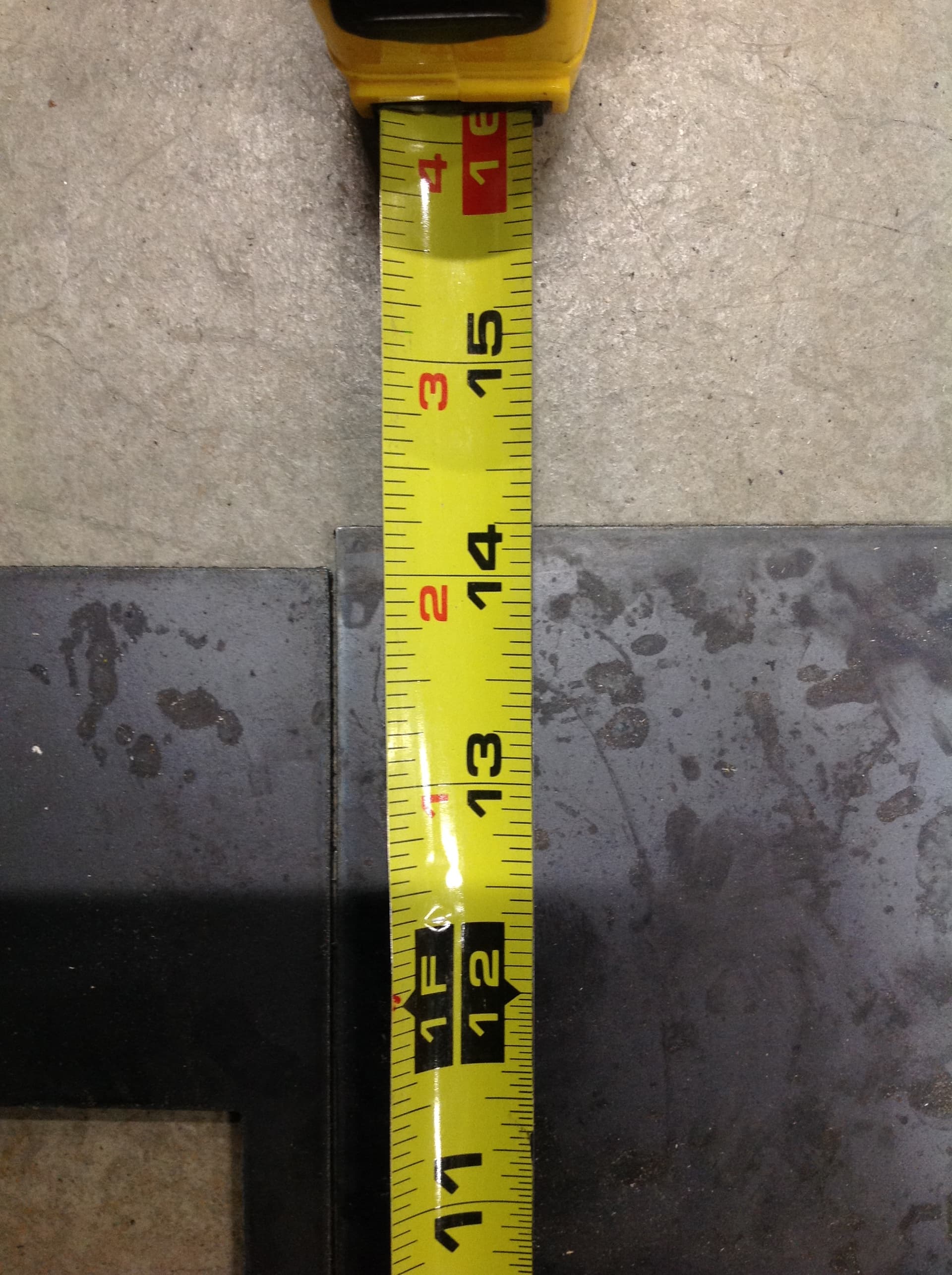
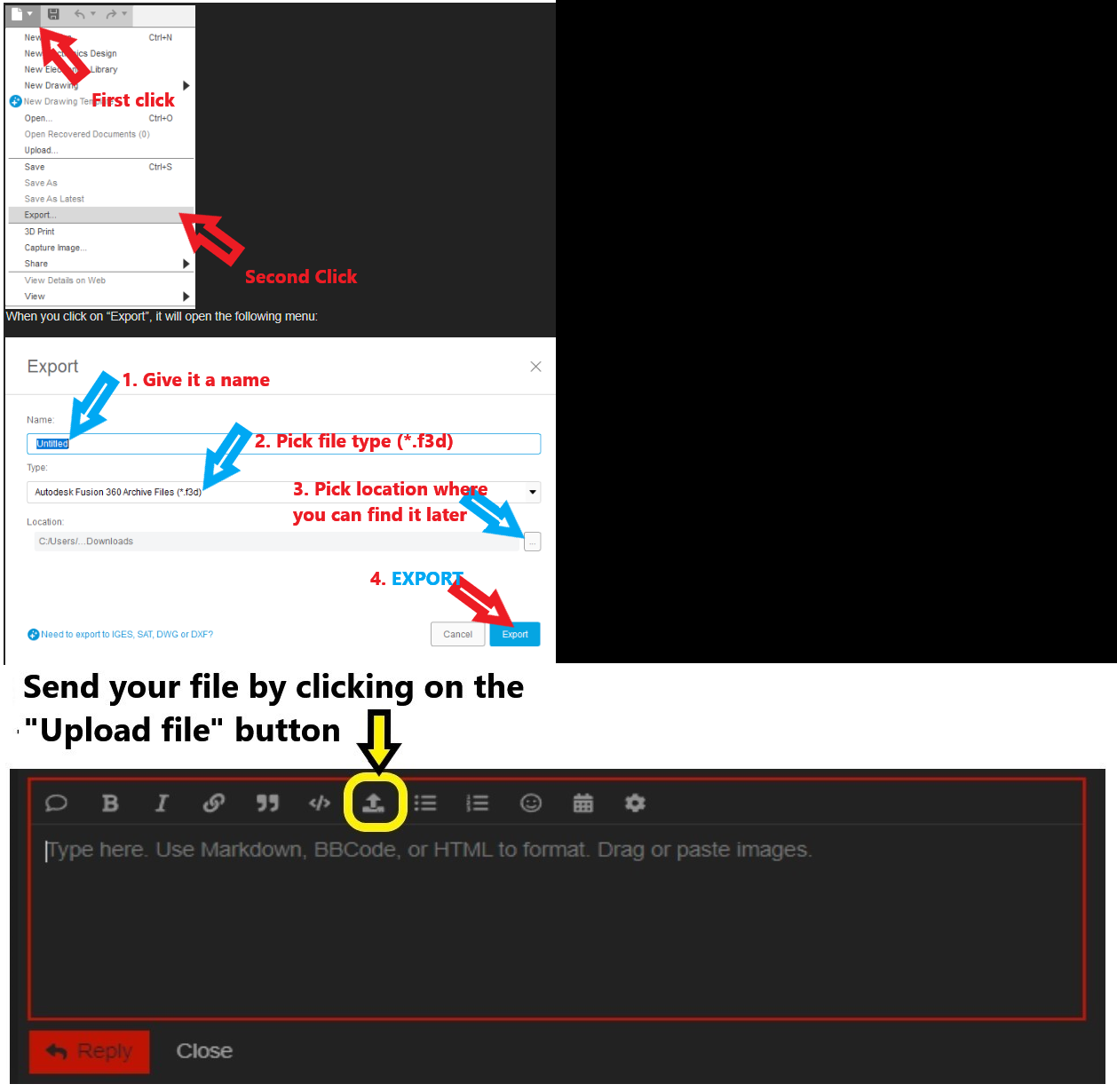
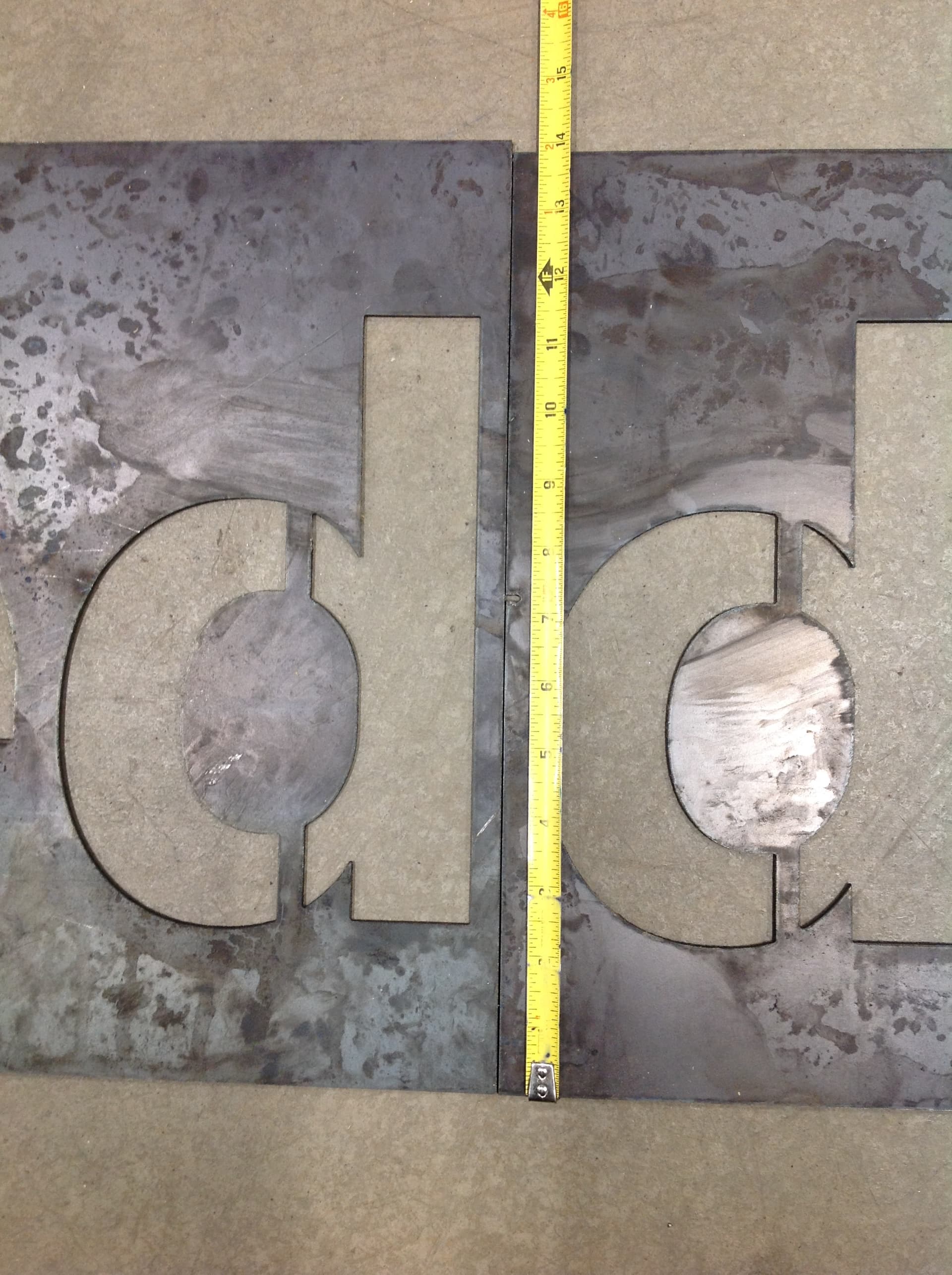
He cut two rows of the sign. There are three rows to the sign, each around 12"-14" tall, and each row is split into sections 2 feet - 4 feet long (4 feet is the longest that fits on our table). One row turned out fine, the height of the adjacent sections may vary by 1/16" - not big enough to be noticeable, so OK. The first two sections of the next row were both about 14" tall, but the third section cut about 1/4" taller. My student said he had them all set to 14" high in Fusion360. Fire Control adjusted the first two sections to 14.0625", but adjusted the last section to 14.3125". I have attached photos that show the height difference between the middle and last sections. I also tried to upload the two f3d files, but I got a message that says “Sorry, new users cannot upload attachments.” Any ideas to get around this?
Any more help would be greatly appreciated! Thank you all for your time and expertise!
It would be good if we could see the f3d file. Now that you are uploading photos, you should be able to upload the f3d file. That is the fusion file that has all the sketches and the manufacturing data that you are using for this particular project.
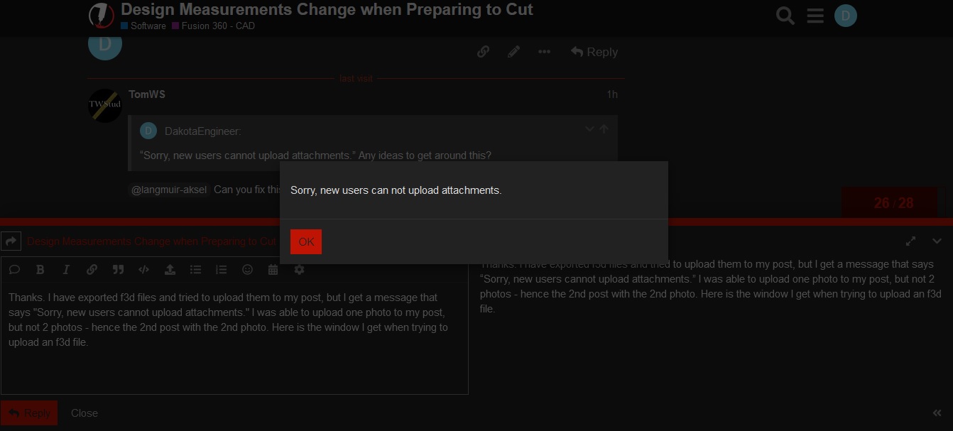
Thanks. I have exported f3d files and tried to upload them to my post, but I get a message that says “Sorry, new users cannot upload attachments.” I was able to upload one photo to my post, but not 2 photos - hence the 2nd post with the 2nd photo. Here is the window I get when trying to upload an f3d file.
That’s just based on how many posts you’ve made. It’s to prevent spammers and bots from hijacking things. The restriction goes away pretty quickly once you demonstrate to Discord that you’re active in an ongoing way and not exhibiting bot-like behavior. By the time we resolve your issue you’ll have “graduated” just by virtue of reading & posting on this thread.
I watched my student’s issue today. In Fusion, he had the sign height set to 14.23"; when he opened that file in Fire Control, the measurement said 14.30". So he changed his Fusion design to read 14.22"; then when he opened that file in Fire Control, it read 14.16". So by reducing it 0.01" in Fusion, Fire Control dropped the height 0.14". (I still can’t attach the file, maybe this post will push me over the threshold.)
That is why we need to look at the sketch and see what numbers you are talking about. When you are saying a measurement in Fusion 360, I am assuming the dimension of a line or side of a box.
I have never looked at FireControl to give me confirmation of my dimensions. As someone mentioned earlier, that dimension is taking into consideration the space that the programmed cut will take up: including offsets and lead-ins/lead-outs.
Jumping in as well, We use Fusion extensively to design for FireControl. I’ve yet to have a finished piece come off with bad dimensions. I can’t say I use the overall dimension box in FireControl for more than just rough dimensions.
Some things that I can see than FireControl would use to generate a different overall size:
Lead in / Lead out - Size and location. If location is undefined, Fusion may place this on an edge you don’t expect. I believe this was mentioned earlier.
Kerf Width - If your width dimension is X, overall width (from the G-code standpoint) would be X + Kerf. (1/2 on each side)
Cut Compensation - Should always be “left.” If your cuts are accidently cutting the outside profile on the inside, your size dimensions will be off.
Setup / Stock Size - If your Fusion Setup has additional stock enabled, your origin point will be away from the cut edges. FireControl will see this as a larger overall size.
I do agree, once you can post the .f3d file, we can get a better understanding.
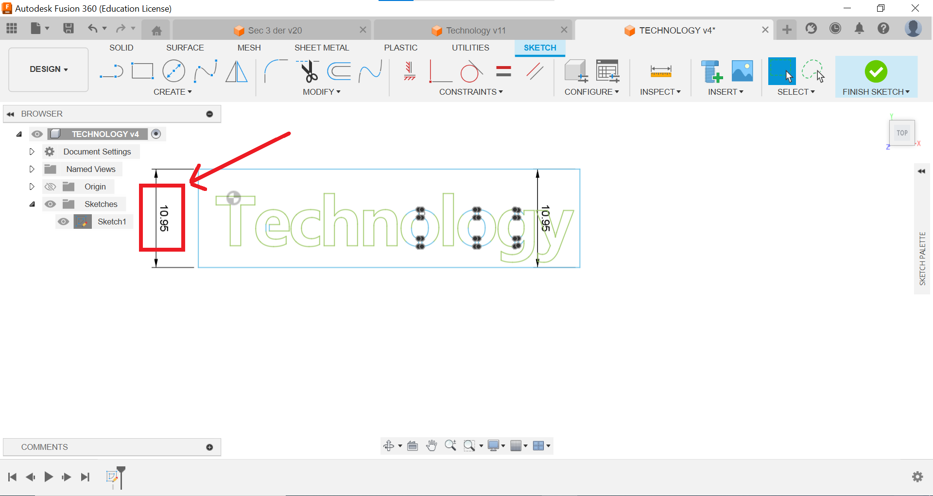
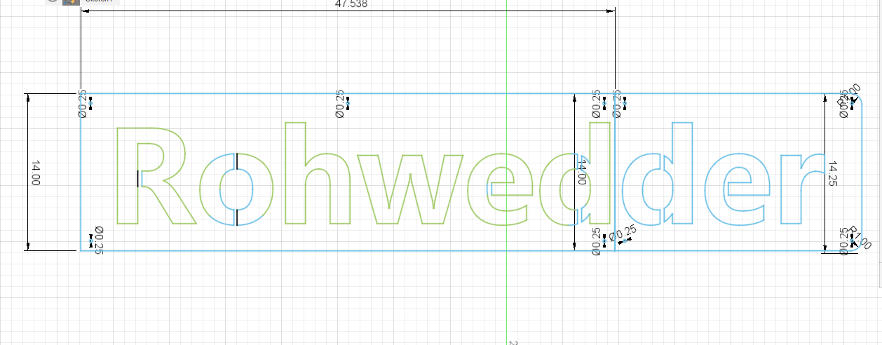
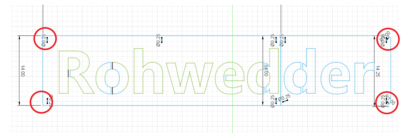
Below are screenshots from Fusion 360 and FireControl of a different section of the sign he was working on that show the dimensions I am referring to (boxed out in red). This one increased from 10.95” to 11.24”, and I understand why because I can see the lead-in on the top edge of the sign in FireControl.
Referring to ChelanJim’s comment about not looking at FireControl for dimension confirmations, I told my student to design the other sign section that had cut a height of about 14.25” (the right side of the sign with the 2nd “d” in the photos in a previous post) to a 14.00” height in Fusion 360, not worry about what FireControl says for the height, cut it, and see if it turns out like the left side of the sign (the 1st “d”) that is about 14.06”. The final piece was about 13.88”, so it got shorter (see photos below).
I have uploaded the two .f3d files with the two sections of the sign with the ds that we are trying to match in height. I don’t know what versions they are – he has modified some of the sections several times to try to get them all to match – but the goal is to make the right part of the sign (“der”) to cut to a final height of 14.0625" so it matches the left side of the sign that is already cut. Sec+2+Rohwed+v8.f3d (226.9 KB) Sec+3+der+v10.f3d (195.5 KB)
I apologize if I don’t always provide all the details of exactly what is happening, but I teach another class while this student is mostly working on his own, so I usually don’t have a chance to observe everything that is happening when he works. But your comments have been very helpful for my understanding, so many thanks to you all! We are hoping to figure this out this week so the sign can be completed and hung next weekend for an event a few days later.
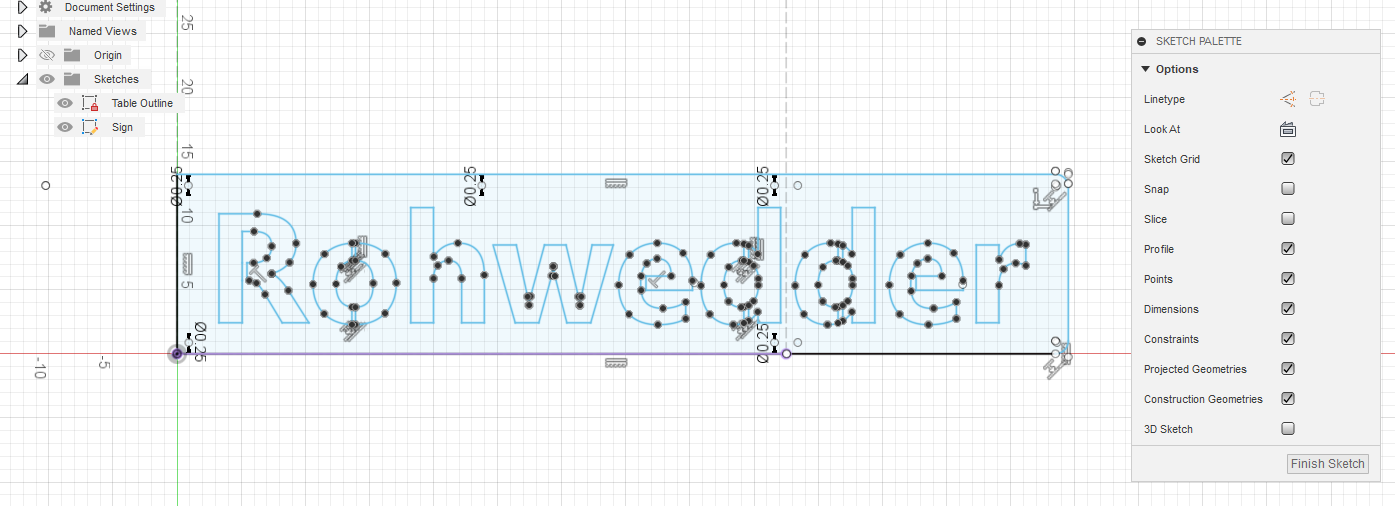
I changed the one dimension of 14.25 and put the “der” in the same position but in two different sketches. Turn on both sketches and you see they match up. Hide one by turning off its visibility:
If you want the final cut height of 14.0625…geesh!!! I don’t know if that is what the first one was.
So this would be with your desired modification (and it is really at 14.0625, I just have it set to only round to the thousands place. If you click on the dimension it will show 14.0625):
I would just recommend that he try to work on the entire sign on one sketch. Fusion 360 has a great splitting tool when you are ready to take the sketch to Manufacturing. That way everything is adjusted at the same time. Then the split maintains all those settings.
One last thought. I don’t know if this is intentional to have rounded corners on the right and square on the left:
When we started this project, we didn’t know how to make separate parts of a sign that were too big for our cutting table. I suggested to my student to make the entire sign in one master file, and see if either…
He can figure out a way to do separate cut paths that only cut out a part of the sign with each run (which I think is part of what you referred to later as splitting). or…
If he couldn’t figure out how to do that, then make several copies of the finished master file with the full sign, and delete what isn’t going to be cut out of each copied file, so there was a separate file for each section of the sign.
I believe he couldn’t figure out the first method, so he went with the 2nd, and then tried to make changes in each copy when needed so they all matched. (I’m guessing there were different adjustments made for different sections unintentionally when moving from Fusion 360 to FireControl.) But it appears you can do method #1 by splitting and turning on/off visibility for separate sketches (we do not know how to do this). I assume we can learn more about how to do so by researching those tools, now that we know what they are called, if those options are available in the Education version of Fusion 360.
The original plan was for the height of all sections of this row to be 14.00", but after cutting, the other sections ended up about 14-1/16" tall, that’s why we are trying for 14.0625 with the “der”.
And yes, the right section is supposed to have rounded corners on the right side and the left section is supposed to have all square corners, because this line of the sign actually has three sections. There is one more section on the far left that has rounded corners on the left side of that section. Thanks for mentioning that, just in case!
I will have my student download the files you posted during the next class period and see what we can do. Thanks again for taking the time to share your expertise; your help has been immeasurable!
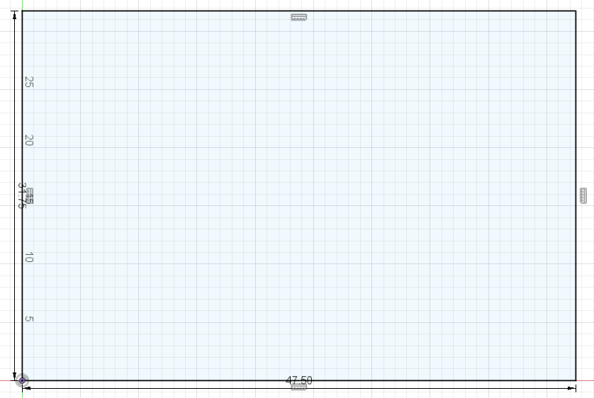
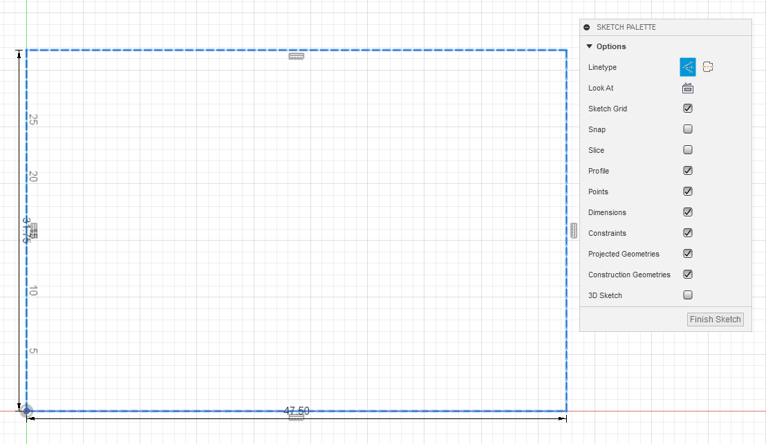
Start your sketch on the XY plane and just trace out the area of the table. I will first just make a rectangle box (the size of the Pro table cutting area):
Double click on one of the lines of the box and it will highlight the entire box. Press “x” and it will change them to construction lines. Construction lines never get cut in Fusion 360 so you can put as many as you want and not worry about Fusion 360 deciding to cut them in Manufacturing. They become dashed lines.
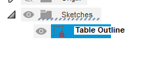
Close out that sketch by pressing “Finish Sketch.” Name the sketch something so you can keep track what sketch does what in your drawing. I named it “Table outline.”
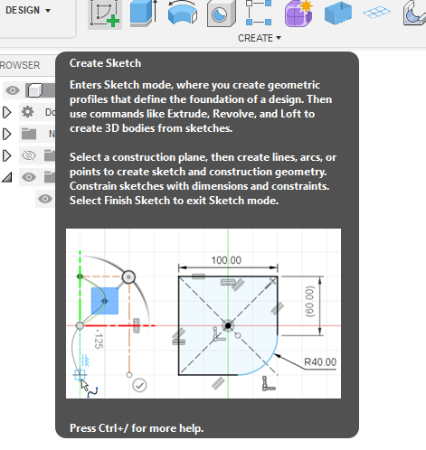
Now open a new sketch on that same plane by clicking on “Create sketch.” We will use the exact same XY plane.
Now design to your hearts content on this sketch and you can reference the dashed lines to know where you are in your available table dimensions.
Once again. Close your sketch by clicking Finish Sketch.
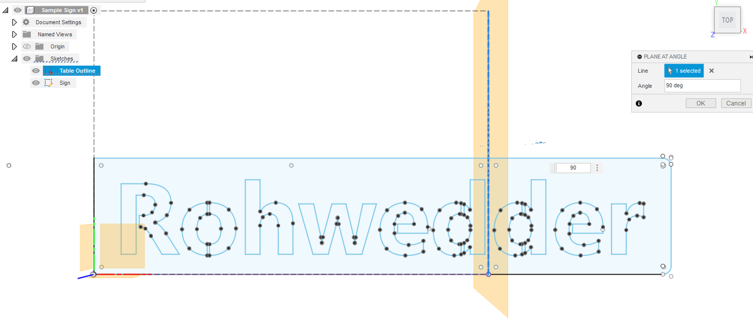
Now comes the preparation for splitting. First, we need to create our splitting tool which will be creating a “plane at an angle” and use the right side construction line as the reference for the plane. When I first click on that line, it gives me a plane that is in line with the current XY plane and has that line incorporated in it. I don’t want that plane. I want one that is exactly 90 degrees to that plane so I type “90” in the angle box.
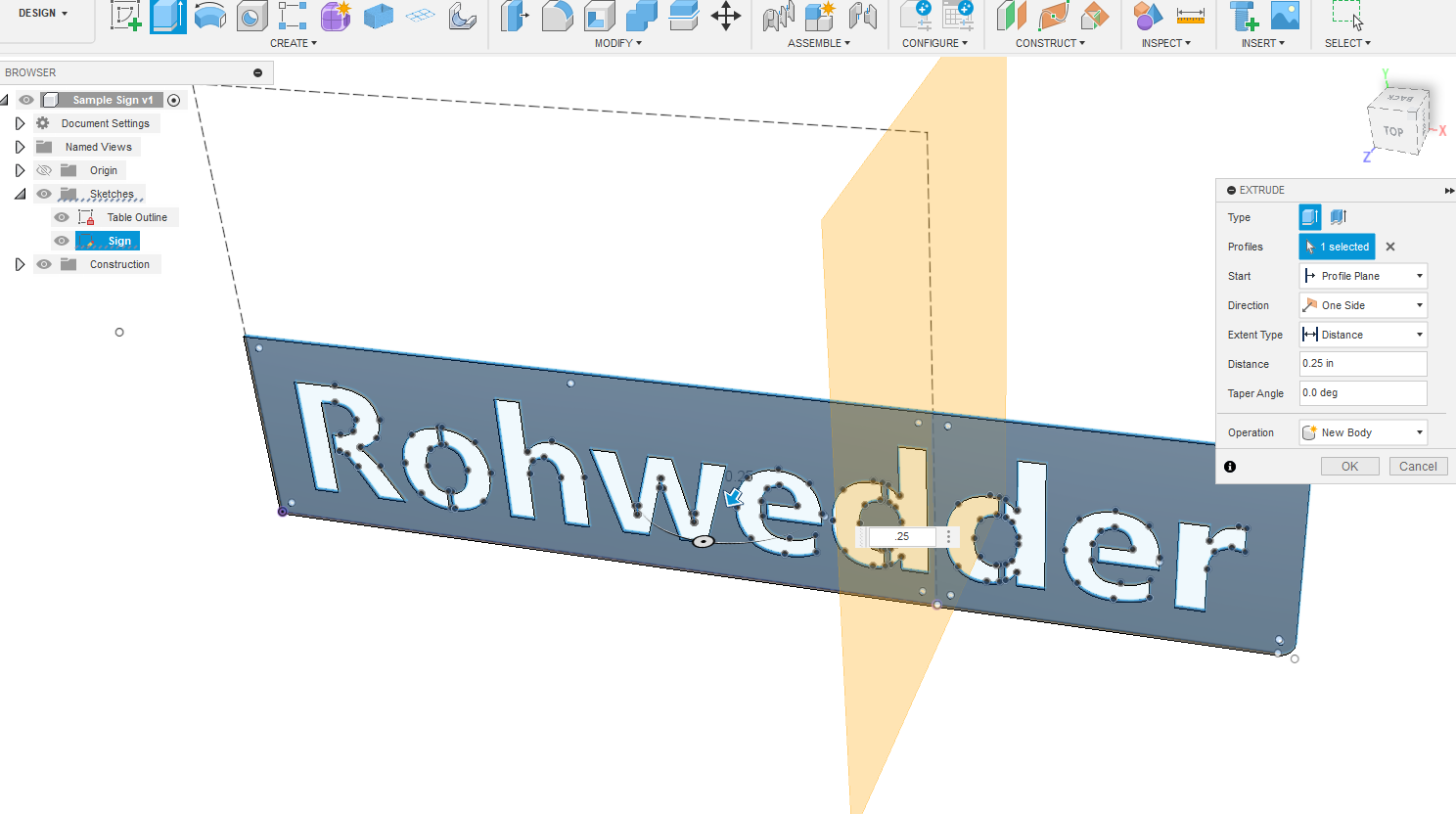
Extrude the body. This will create one big sign. I made this sign 0.25 inches thick. It really does not matter how thick it is. Fusion 360 won’t care. I did “0.25” because it is visually easier to see that it is a body with this large of an object. (It is easier to see what you are doing with the extrusion if you rotate your image slightly [SHIFT][Middle Mouse button-wheel] then move the mouse).
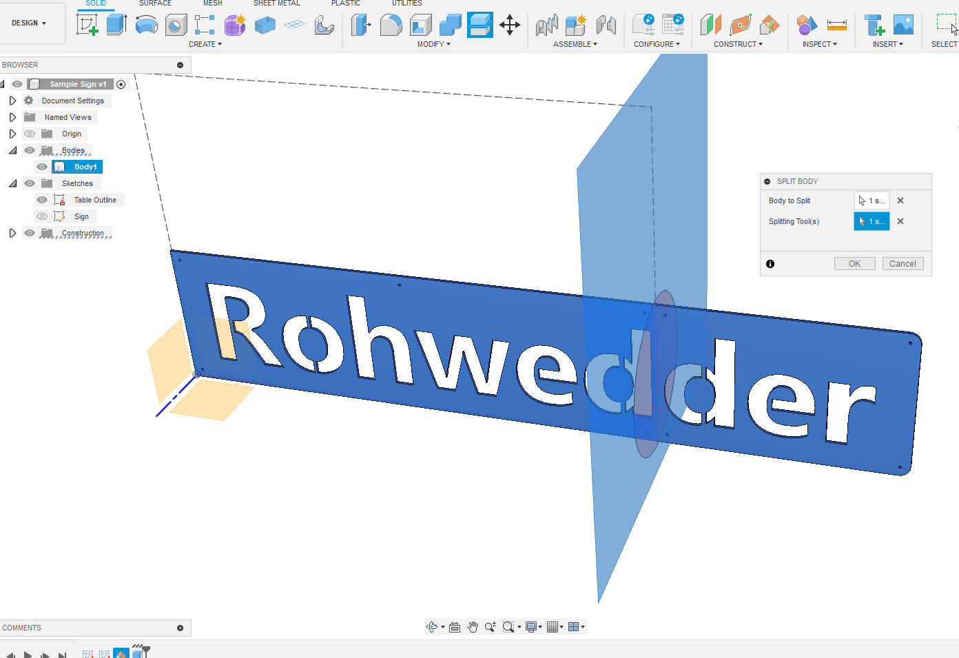
Notice that you now have a body on the file browser on the left. It is showing only one body. Time to split it. We will pick the body that we want to split and use the construction plane that we created earlier to split it.
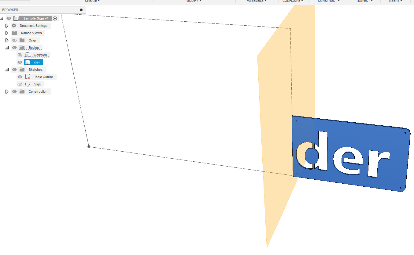
Now we have two bodies. They can now be used independently when you go to manufacturing. You can leave them both on as it is easy to differentiate in Manufacturing or you can turn one off just so you don’t get confused. Notice I renamed the bodies so you can easily tell what each body represents.
Thank you so much for writing the steps out for that - I have saved it in case one of the students does another project that is bigger than our table.
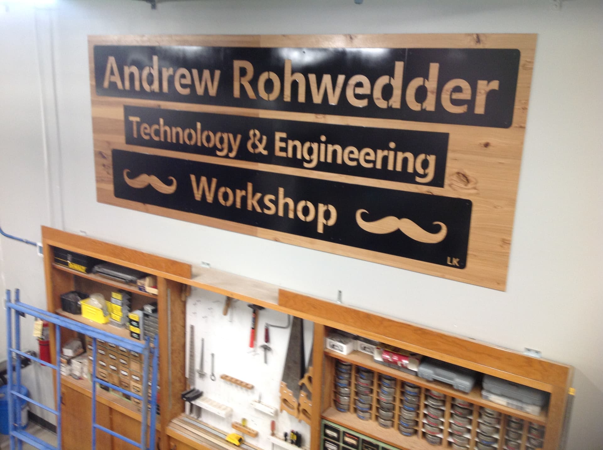
I know it’s been awhile since I’ve posted about this project. That’s because we finished the project during the last few days of our school year, and I’ve been busy doing some other things since then. But I wanted to thank all of you who provided tips/advice and helped us problem solve. It was very helpful during our special project.
The 11’ x 4’ sign we were working on was to name the workshop after the former shop/tech/engineering teacher at the school. He taught here for 41 years before he retired about 6 years ago. I was one of his students, and I wanted to find a way to honor his contributions. We had a surprise ceremony - he didn’t know what was happening. We had the sign covered with plastic, and after I talked about the new machine and the student’s efforts to complete the project, the student cut some strings so the plastic dropped and the sign was revealed to the room full of current students and the teacher’s former coworkers. There were a lot of oohs and applause. The former teacher was very surprised and appreciative. He said he had a sign for his workshop that was given to him in the past, but this one was better. We were able to fix some of the height issues between the panels that were obvious, but we just ground the others that were very close so they weren’t so observable, and it’s hard to notice them now. Your tips helped my student continue on when he was extremely frustrated with the software and I thought he was going to stop working on the project, so thanks again for your help!