I don’t know how many people have heard about the Jacob’s and co Bugattis watch. It has to be one of the coolest things to ever be made. On their website it shows little short videos on how the machined them. They used a 5 axis machine to make the casing of the watch. I’m relatively certain that it can be done without a 4th or 5th axis. I know that I really want to make one but being relatively bad at CAD so I have absolutely no clue how to start the cad process for just the shell of the watch. If yall could provide help that would be great.
This is the link to the video of them machining the case for it.
Thanks
Not really knowing anything about the watch and very little about 4th and 5th axis, the way I approach most of my 3D models is by additive and subtractive extrusions.
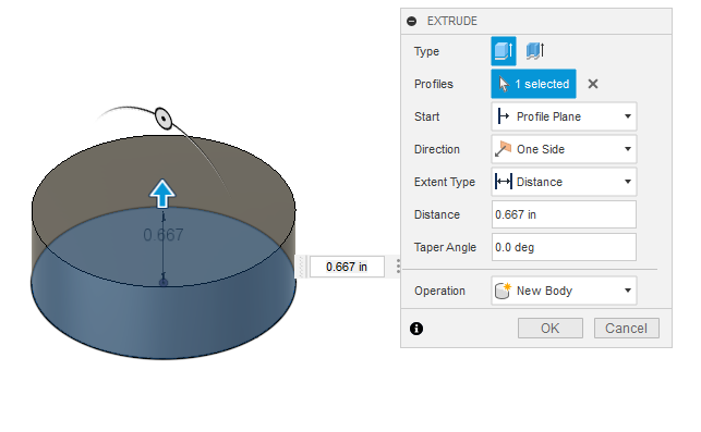
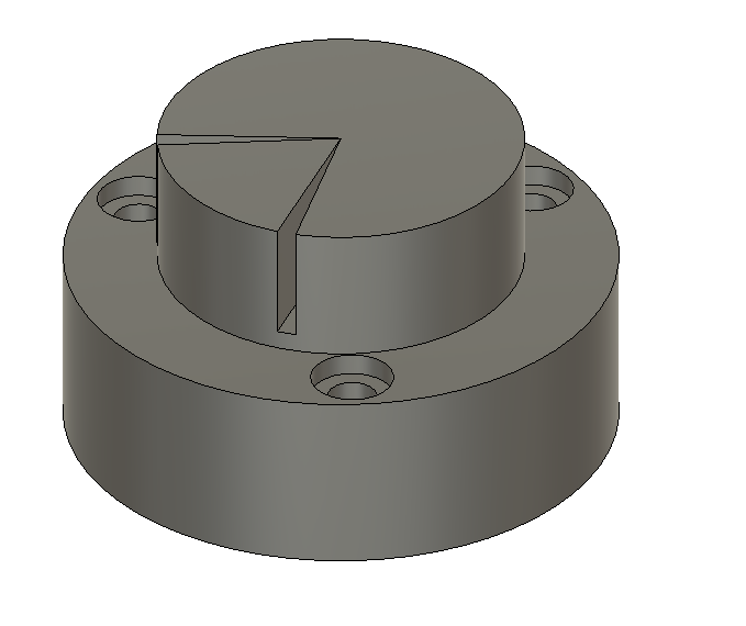
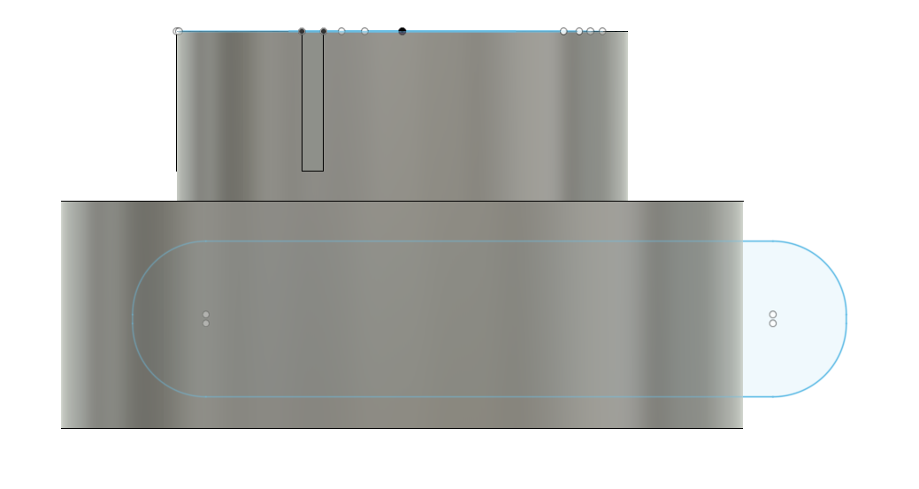
I have to start somewhere so I make a base:
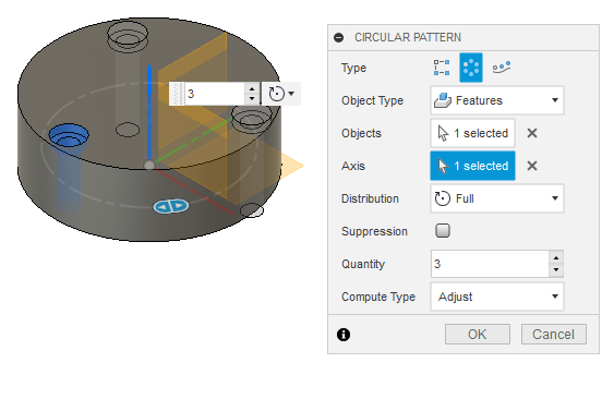
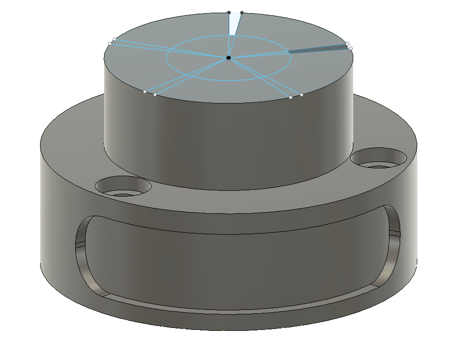
Now I want a screw hole. I make one and then create a circular pattern:
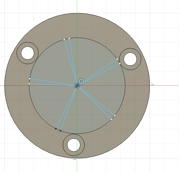
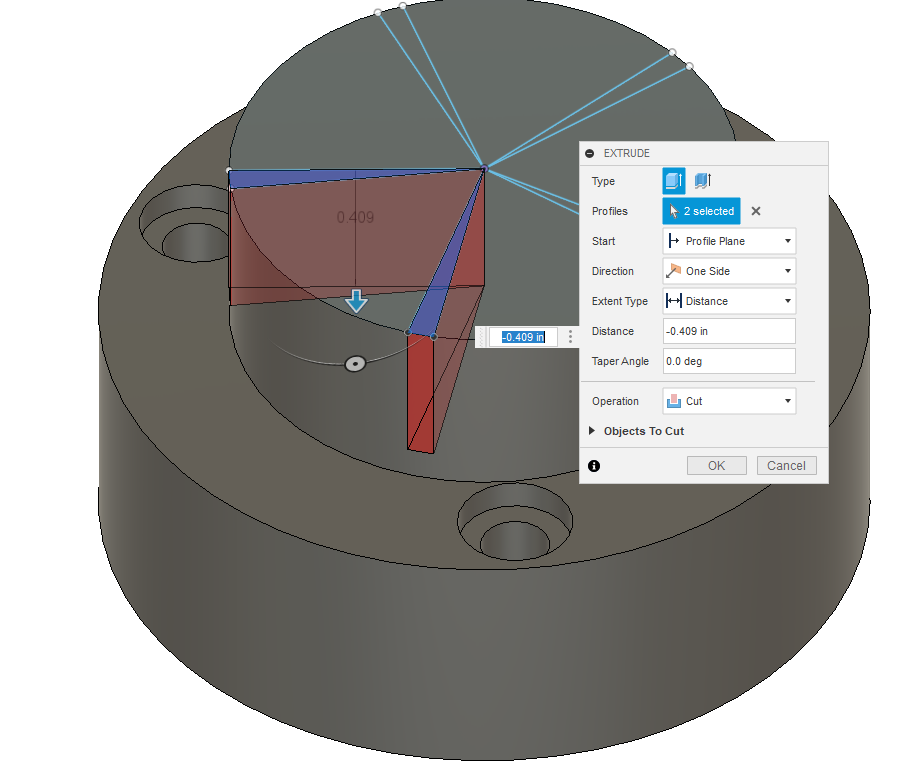
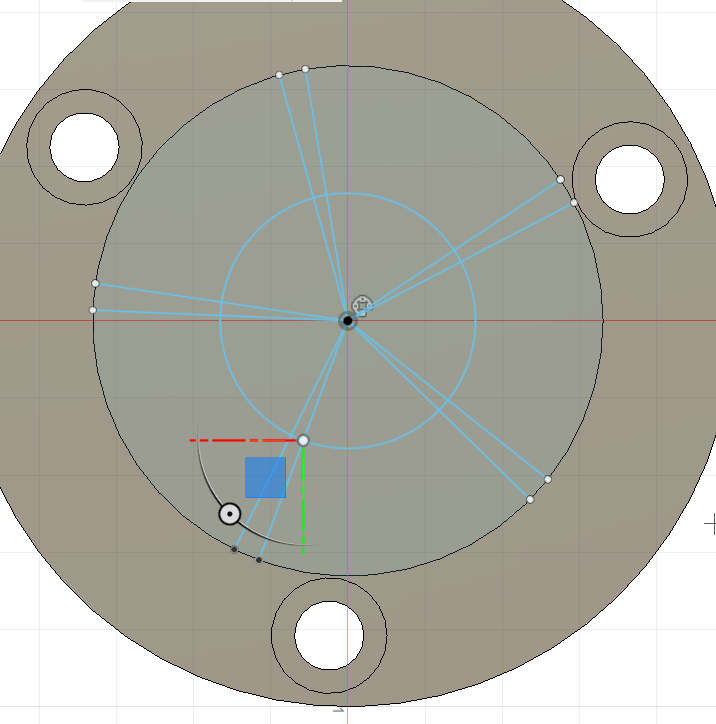
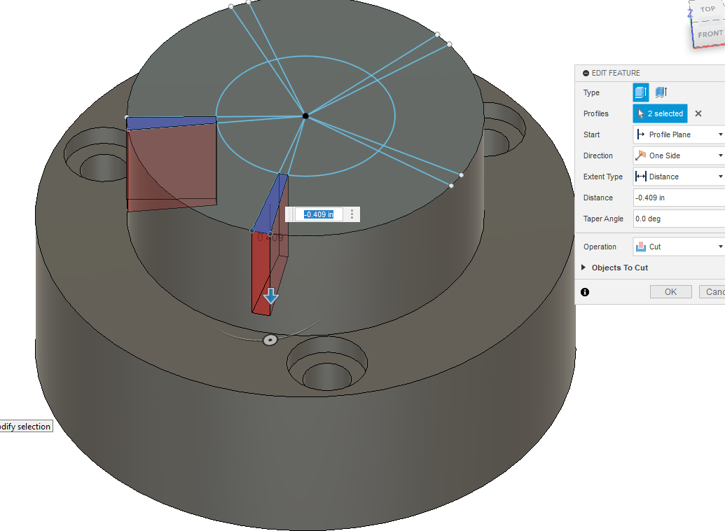
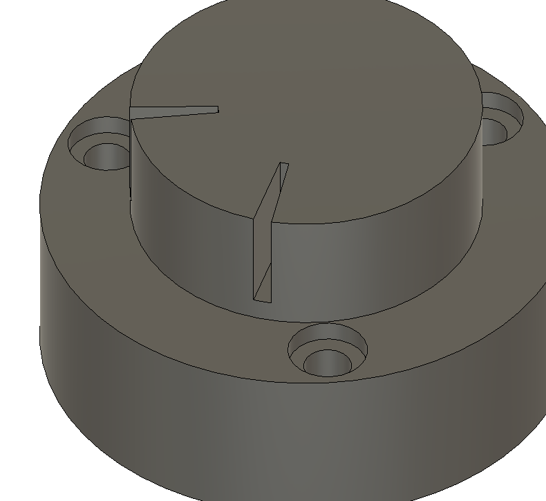
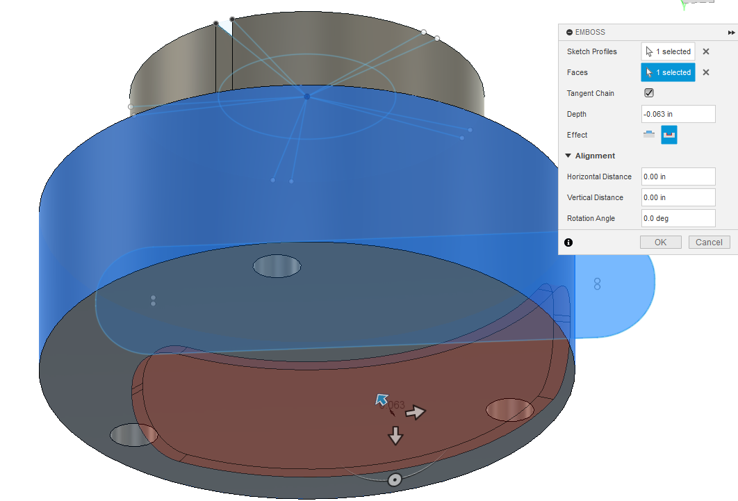
Now adding the next stage, I draw another sketch on top of the previous part. Extrude. Draw another sketch on top of that to cut some areas out:
Thank for your response. I think I have gotten down what you are talking about the only thing I seem to have problems with is creating super smooth curvy object like on the watch. Thanks again for the response
There’d be a lot of time and effort that would go into recreating that watch even just recreating the frame of that watch.
If you want to recreate the frame of that watch you’re going to need to start with some good views of the side bottom top with as straight on of a shot as you can get it.
And then I would model it using canvases in fusion 360.
Likely many different techniques are going to need to be put together.
I see the one from the screenshot is the diamond encrusted edition so it has all the bed cut into it for the settings.
Out of curiosity why are you recreating this watch form or is it just an example of something you’d like to do?
There is an STL file available online for this entire watch.
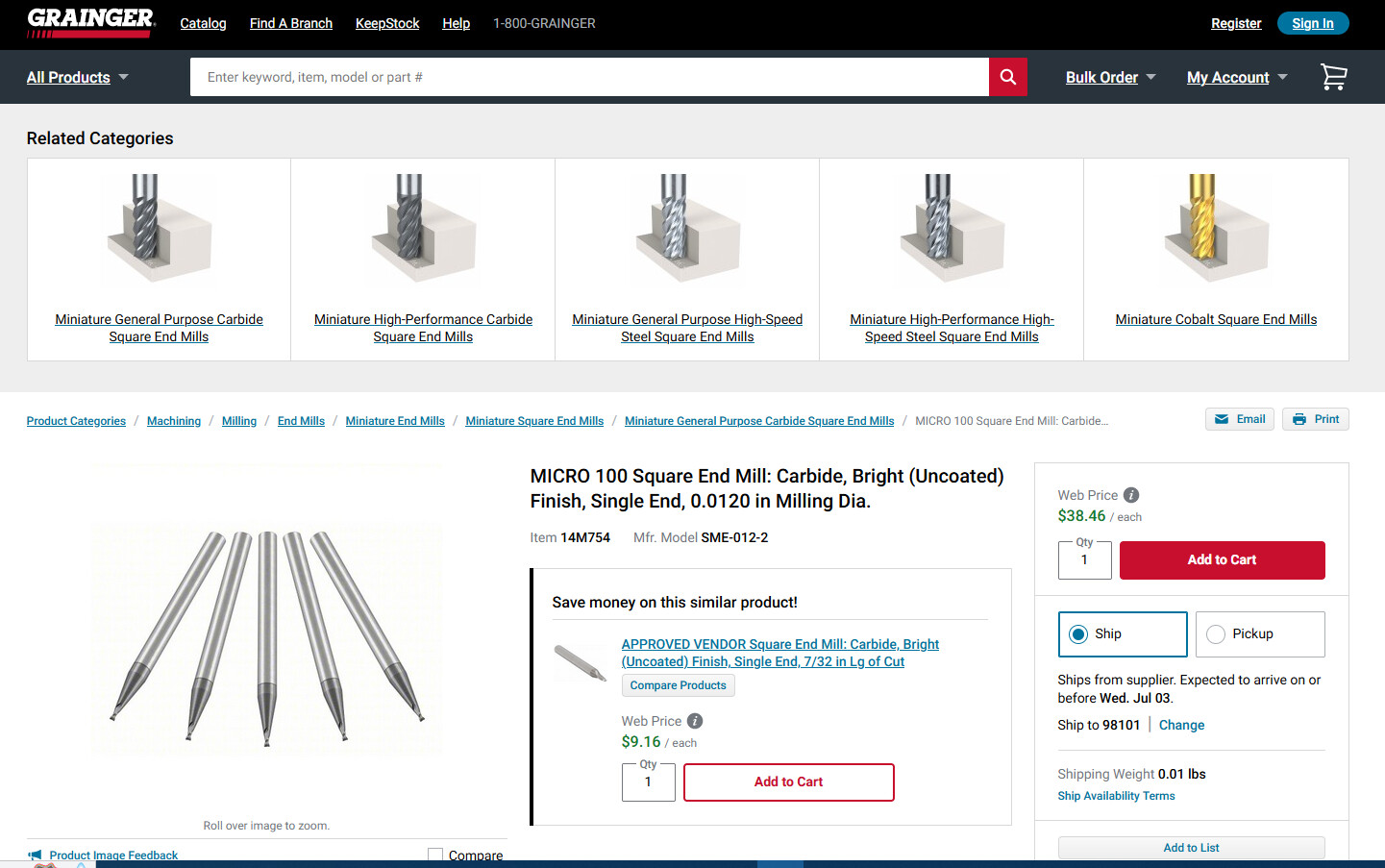
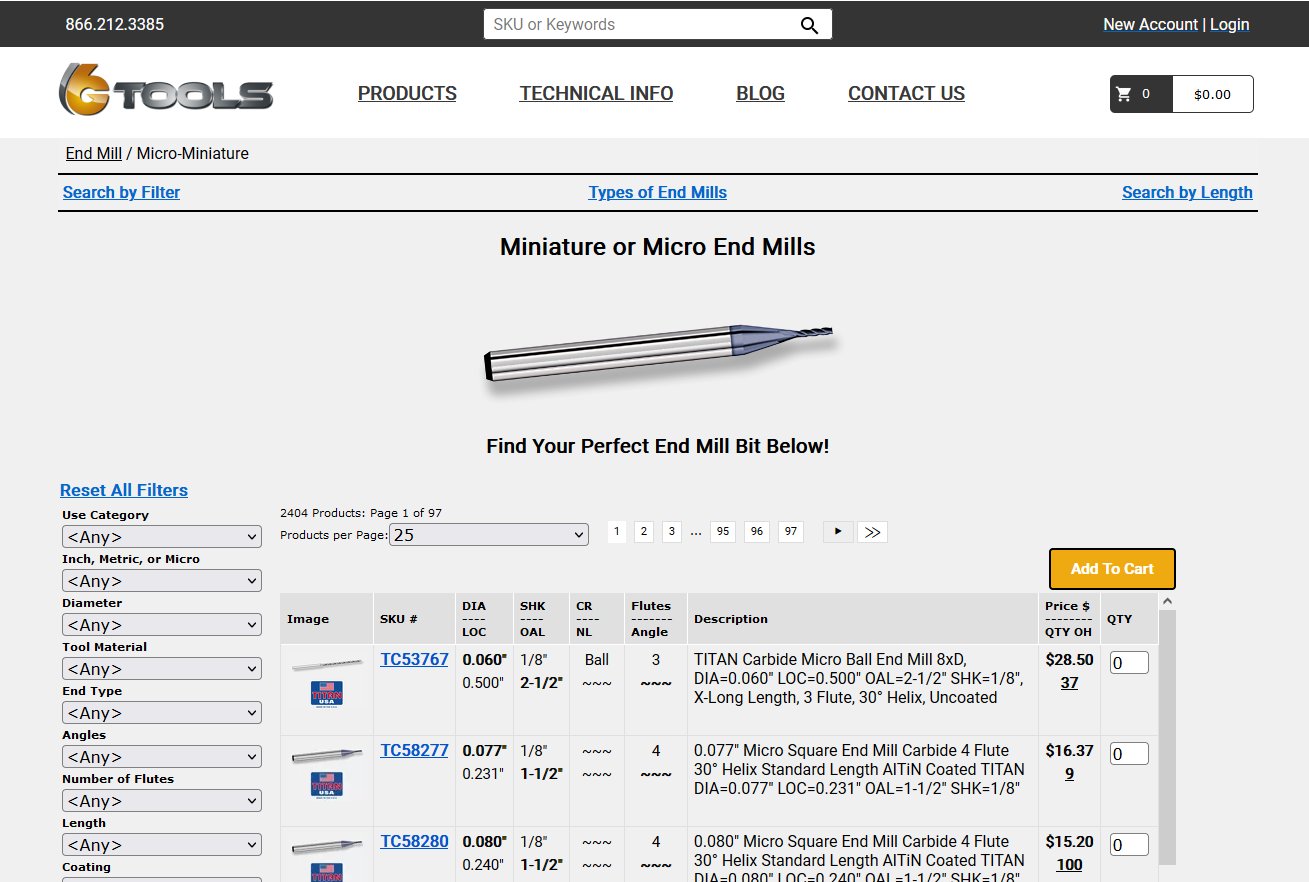
The reason I’m trying to recreate it is because I want to try and make a full one on the mr1 to really learn the machine. Do you know where I can get these small bits?
If you were ever in need of a new occupation I think you would make a killing setting up a Google-type web search engine for all things related to manufacturing and manuals.
Not sure if this would be small enough. They probably have their own source that makes their milling ‘bits’ specifically for them or have their own company that does it to keep it proprietary.
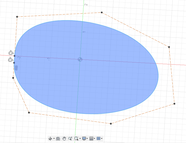
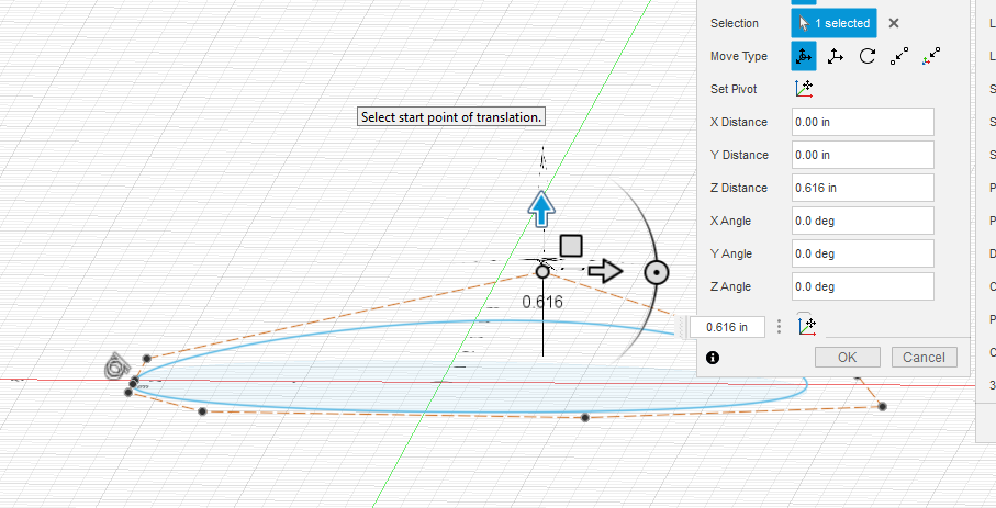
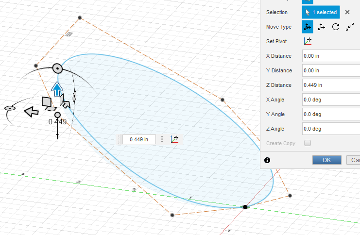
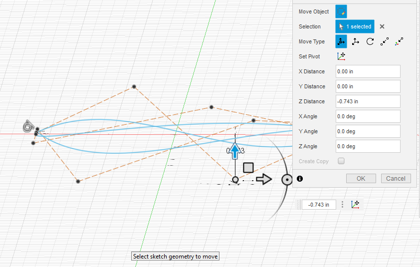
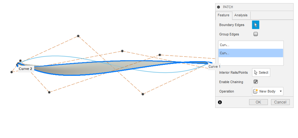
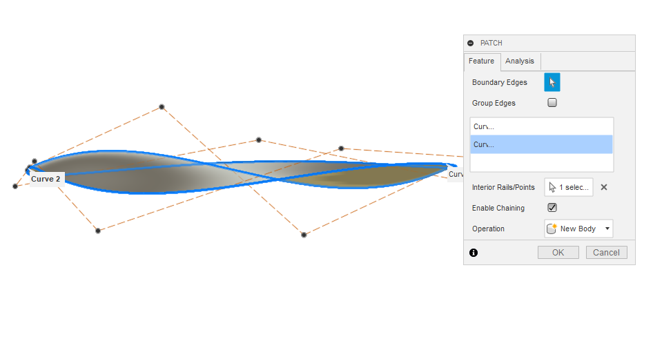
For smooth surfaces, you want to use the surface tool. I have not done a lot of this but for me it seems to do best with “control point spline” tool. First you make the outside circumference like you want, perhaps using a canvas like Tin suggested.
Still might not be what you want. I think Tin’s advice is sound: it will take considerable time to get the end product you are looking for and the fact that someone has already done and offered the STL file is major.
If you add the person’s profile name to your message, they will get and special alert. To do that just type “@” and usually all the people involved the the topic will appear in a drop-down menu.
So for this topic if I type @, and this appears:
Tin is really good of following up with messages but I will include his name here and he will get back to you. It might not be until this evening or early in the morning. @TinWhisperer
I expect that the level of detail on this watch likely requires accuracy that is out of the realm of the MR-1. Ironically small and highly detailed projects can be a very difficult way to learn. Small cutters like that are very sensitive to speeds&feeds and machine quality – slight collet runout on a 1/8" endmill isn’t a big deal, but can destroy a 0.5mm (20 thou) endmill in a hurry.