Brand new; have many questions starting with Fusion 360

Hello everyone. I am an older (71) retired engineer and life long amateur mechanic. I’ve just set up my Crossfire table (extended with water table and Z axis) and I am TRYING to work through the Fusion 360 tutorials to make my first cut.

I am getting hung up on the differences between the version of Fusion shown in the tutorials and the one I just downloaded. FOR EXAMPLE: I want to radius the corners of the bottle opener Langmuir uses as a teaching example and I CANNOT find the right tool.
I have NO previous experience with CAD so I am pretty much a child just playing with blocks. I’m sure that adds to my inability to make this work.

Is there EITHER another tutorial set for Fusion that’s more up to date so that I can DO as I SEE? Or another, maybe more basic but useable, CAD tool to use with the Crossfire?

@oldsubsailor Welcome to the forum.

The interface interface for Fusion is being continually updated and some of those video were made some time ago.

Check out these videos on fusion’s sketch environment from Productdesignonlines page .

Also I created a small series that is plasma focused.

There is quite a learning curve to start with fusion but with time it can be great to use.

4 Likes

Old Sub I would grab Cletus’s test file off of fireshare to run your first cut.

https://www.langmuirsystems.com/fireshare/test-card

It’s known to work and will give you a way to dial in your settings. If you really want to start with your own file I would make it really simple like a circle, square or triangle. Keep it simple and progress slowly with both fusion and the table. The files on fireshare are also wildcards some are good and some, not so good. This table can be a lot of fun but also very frustrating if you try to move too fast with either the software or complexity of the cuts. This forum will be a lot of help if you ask.

2 Likes

Is this what you wish to do ?

Fillets are done in SKETCH MODE


To fillet corners, go to Modify menu / fillet
Click corner to be rounded…

Try that.

1 Like

Filets can be done on a 3D body as well. In fact, I prefer to do it to the 3D model/body because it then ends up in the timeline and is easier to edit.

2 Likes

I re-read this and it leaves me wondering if you’re attempting to edit the G-code file you may have gotten off of file share? If that’s the case you will definitely drive yourself crazy. What is the file extension of the file you’re trying to edit? Is it a .tap? If so you can’t easily edit that in fusion. Tell us more about the situation and you’ll get some feedback that can hopefully help.

OK… so I finally tried to download the file to save it for use tomorrow. The system said I had to log in. OK… I tried to using the email and password I set up to get to this forum in the first place and the response was that my login was invalid. ???

I am getting frustrated … I hate it when tools fight me for basic stuff.

Honestly not sure what to try next… say that I ‘forgot’ my password ???

Evening Dave… So, your login for FireShare will be different from the one you use to get to this forum page. Not sure why they are not linked but, that’s the way it’s always been…

GL

1 Like

Thanks… yeah, I just (sorta) figured that out. Created a unique login and got the file downloaded.

I have to drop out of this exchange for the evening… priority interrupt (wife)…

back tomorrow hopefully

1 Like

Take a look at this

Also if you post a question In here looking for help check back often as people are always on here answering questions.

Im 65 and trust me learing the Software is huge!!!

1 Like

Welcome. There are many of us that are over 65 and learning this stuff with each other’s help. This forum has been very helpful for me and people really care about helping.

Everyone has a different path to learning. I tend to be more visual so I really felt inspired to learn Fusion360 from YouTubers like NTD Racing and Mike Festiva. If you see a topic that you are trying to learn and Lars Christensen is doing it, it is worth a look. What I usually search for is: Fusion360 topic you want like: rounding corners.

Now rounding corners is an interesting topic: Mike Festiva advice is to keep a copy of your drawings without fillets as it is more challenging to undo the fillets. Just recently I saw a video done by Tin and he showed how it is quite easy to undo fillets by extending the lines. That is what I mean, you might think you want to learn one thing and these people teach you those ‘secrets.’

@TinWhisperer is a wizard with Fusion360. If you win the lottery, he will do a recorded lecture on a topic that you are stumped or just wanting to learn more. Every time I watch Tin, I learn not only the topic he is teaching but you see some of the other features that are in Fusion360 offers in a real life application. You cannot stump Tin. 99% of the time, he either knows it or it can’t be done.

I am not going to name drop anymore but you will quickly feel welcomed and cared for by this group.
Enjoy your evening.

4 Likes

OK, it’s been a few days so I thought I should check in an let you all know I have not given up on getting my table set up and tested. To explain briefly: we’re nearing the end of a very long kitchen remodel project and I am having to spend time with various contractors so I have been, and will be for a while yet, spending time on my Plasma table project in bits and pieces. I did get some wiring changes made and the table moved to where I expect to use it in my shop.

Along the way I’ve added still more to my many questions. One that occurred to me when I was moving things is this: I have a Hypertherm 45 with a machine torch to use with the Langmuir system. It includes the Z-axis / THC add-on. Do I use a drag cut shield on the torch ?

No. You would use the shield that lacks the projections. Your machine torch should have come with the appropriate shield. The projections on the drag shield are meant to be touching the material. You won’t need that since the system will determine and regulate the height.

As a matter of fact, if you tried to use the drag shield, IHC would react to it touching down and consider it at Z=0.0. It would then raise the torch up to the torch height clearance setting and would be twice the height you would want.

1 Like

Thanks, that’s what I suspected but wanted to verify it.

OK… so as of this evening I believe I have my table physically set up & ready (power, dry air supply, dedicated laptop). And, per the advice I got here, I have the TEST file down loaded and available.

In an attempt to get a better understanding of the overall flow of how to use the table and actually test it using that file, I decided to go back and just watch through the tutorials on CAM since I’m not trying to create a runnable file from scratch. I am having a very hard time wrapping my (old) head around the entire process from end to end to wind up with a mental image of it all. Is there some kind of a flow chart like diagram of it all?

One thing I think I understand is that somehow I will have to get the torch to the HOME location on the test coupon so that the run script (probably not the correct name, but I think you know what I mean) knows where to start from. I know from playing with the Firecontrol software that there is both a table HOME and a work piece HOME that’s configurable. The note in the picture posted with the test file says “start at the center of the circles smaller than 0.125 inches.” I assume that, that location would be HOME on the workpiece. But WHICH circle do I declare to be the one to start at?

Keep in mind, this is what has been working for me. Others have their own methods:

The limit switch is still really new and I still get errors telling me I am outside of the parameters. If you get that warning simply touch the “Home” button in FireControl and it will then warn you that it is going to home the machine. It will home in the left back corner and stop. At that point, you are then free to move the torch with the x and y buttons on FireControl. You should probably back the speed down from 300 ipm to 100 ipm until you get more familiar with it.

Stop the torch approximately where you expect your project to burn. The next steps will tell the machine you are meant to be in the area: Click on “Set Program Origin”. You can pick one of the corners or the center of the project. You will pick what fits with where you suspect your torch is right now and will be located when it starts the program. Before you do anything else, click “zero all axes”. These steps can be done in the opposite order: zero axes and the program origin if you like.

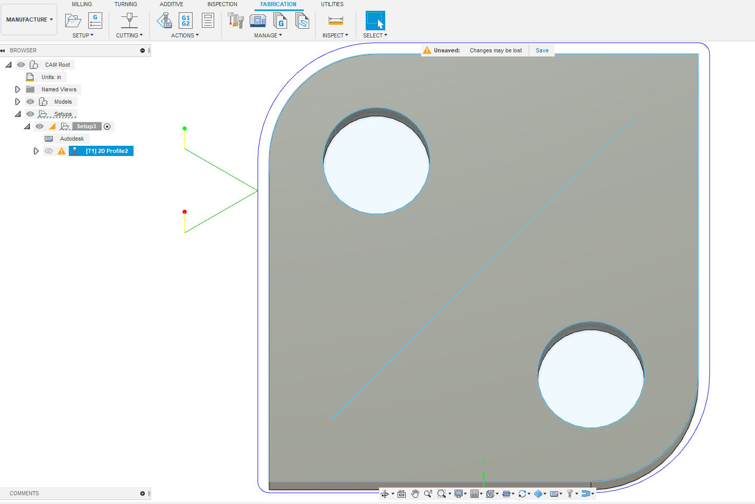
The torch start position is not where the torch starts its first burn. It is just how you tell the program where you expect that corner of the project to be on the metal. The “manufacture” space in Fusion 360 would show you where the first burn happens if you ran the animated sequence. No matter, you will also be able to see on FireControl graphic. I still have trouble reading some of those graphics. (I have lots of floaters in my vision so it is difficult for me to see fine lines on that 12 inch wide screen.)

So you have your air connected to the plasma cutter, the work lead is attached to the metal, plasma cutter is turned on. You have your shade glasses.

The best thing that you can do, to ease your stress, is to click, “Go to Work Zero” (not necessary if you are already at x= 0.0, y= 0.0), “DRY RUN” and then “START.” That will run the entire program without actually firing the torch. If that goes fine then you know you are over metal and within the boundaries. To start the sequence for real, turn off the “Dry Run”, click on “Go To Work Zero”, “Start”.

I was very nervous with my first firing. It is louder than I expected and be prepared for the water to be spraying everywhere when the burn is done. The torch stops and the air continues blowing for about 20 seconds to cool down the torch, so if the air is not restricted by any metal and it is near an edge of the table, you will have lots of water on the floor.

Edit: To limit the water splashing at the end you can do one of two things: 1. slide a scrap piece of metal between the torch and the water tray; or 2. Move the torch with torch control on FireControl. DO NOT turn off the plasma cutter or the air. The cool down cycle is to protect the equipment.

As I always say: “If you don’t make some mistakes, you are not learning anything.” I have never said that but that is how many of us have learned a lot of things. I am sure I missed something but when it happens I will say “Oh yes, that needs to be done too.”

I think you can disregard that instruction. That was one of the topics on this forum. G-code has already decided where it is going to start. You simply need to tell FireControl where the image is going to be on the metal. The rest is all magic and carved in digital stone.

3 Likes

Thank you very VERY much for the detailed reply. Something like the dry run approach is what I was hoping to do first.

Now that I have your well detailed guidance I am anxious to try it… BUT not too long after my last post, the general contractor working on my kitchen project found an error, that can’t be easily reversed, that was made by one of the suppliers (some doors were manufactured shorter than expected). Now I have to spend some time on a workaround. So I WILL be back; just don’t know when.

Thanks again VERY much.

I am at LONG LAST getting back to my plasma table set up today (long story made short: correcting the error made by one of my vendors for our kitchen remodel required MUCH more time than I’d hoped)… anyway, back to the table:

I started working through your excellent set of instructions when I ran into the sort of snag that a newbie like me can hit. The information file provided with the test card file is a .DXF file type but Fire Control does not recognize it because it’s not a Gcode file. I searched and found that there are programs out there to convert a DXF file to GCode … is that what I need to do

That is correct.

I am going to give you a version whereby you would use Fusion360. You have your .dxf file and you know where to find it.

  1. Open up Fusion 360 and begin a new sketch.

  2. Pick the “top” plane.

  3. Insert (under the topic insert you will see a drop down menu): pick Insert DXF

  4. In the “Insert DXF” dialog box, you with pick the folder icon to find your file. After a brief wait, you will see that it is still not picking “your plane.” Simply click on the orange/yellow square in the middle of the sketch and it the image should appear.

  5. What ever else the dialog box is asking, we will ignore and simply click OK in the example. I did not need to change anything to move where you need us to go.

Now we need to close the sketch “Finish Sketch” and extrude the object. Press “E” and the extrude dialog comes up.

It is looking for you to pick the object so click in the middle of the test square. Now it is asking for how thick of piece to you want to make it so type in “-0.25". You could pick “.25" but then you won’t be able to see the sketch. You will need visibility of the sketch to manufacture the diagonal line but in this exampe we are going to skip that part for simplicity of this demonstration.

Now we are ready to go to the “Manufacturing”. Click on the word “Design” with the menu icon and change it to “Manufacturing.” Now here is where you will probably run into some problems. The first menu item that you will need to address is the “Setup.”
FireControl

The first item in the Setup dialogue box is asking what your machine is. You need to find “Generic Cutting Machine: Post: FireControl-v1.6.cps”. Look in the Langmuir website of Video help files of getting started with Fusion360 to get this set up right.

Now you will go to Model in the same setup dialogue box. Click on it and then click on “model”. If your test piece changes color to blue then you have the object already selected. If not click on your object (the “body” created with extruding). You can click on it anyway and see what happens. One click it is selected another click and it is deselected. No harm just make sure there is an “x” next to the “model” in the dialogue box otherwise it is telling you that nothing has been selected.

On the top row of this same dialogue box, you will pick the last tab “Post Process”. In the box of “Program Name/Number” enter what you would like to call it. Click okay.

Now you click on “Turning” and here is another hiccup, perhaps. It will be looking for your tools that you are going to cut with. The dialogue box is titled: “2D Profile.” The first item you will need to answer will be “Tool”. Again, I believe the Langmuir website will be able to help or YouTube. In my example I am picking “my” tool for plasma cutting for 16 gauge mild steel.

Continuing in the 2D Profile sub menu you will move to the second tab: Geometry. In this example, for “contour selection” we are just going to click on our object/body and let Fusion 360 try to make sense of it.
And then click Okay. After a brief wait, you will see what Fusion plans to cut. In this example it failed because of other settings that I purposely ignored. Now we will go fix them. The reason Fusion360 ignored the holes is because the lead-in and lead-out would not fit into the holes.

2 Likes