Hey guys, having an issue with re-drilling a set of rotors. A popular budget upgrade for the car I’m building is to swap out the calipers and rotors for those from a 300zx TT. The original bolt pattern is 4x114.3 and the 300zx is 5x114.3. Easy enough that you end up reusing one of the holes on the 5 lug rotor and just drill 3 more. Should be very simple I know, but I am kinda new to Fusion 360 and am having some trouble.
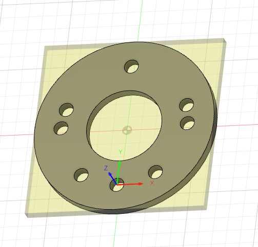
So instead of making it a drilling operation I decided to use a end mill and make it a boring operation. Basically just because I have good carbide end mills and my drill bits not so much lol. Now because I am a Fusion 360 rookie I decided to cut out a template of my bolt hole circle patter on my plasma table and just hold it over an old 300zx rotor that has had a 4x114.3 pattern drilled into it, and to hold it over the new rotor. Just to confirm the dimensions in the model and get a visual. Looks great, shouldn’t have any issue.
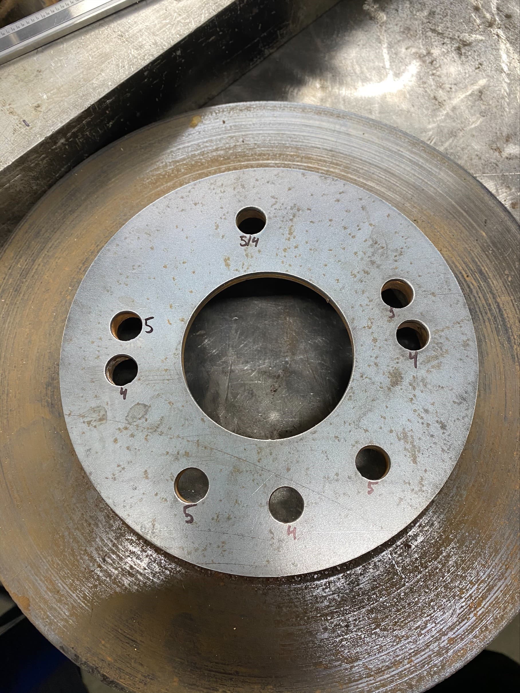
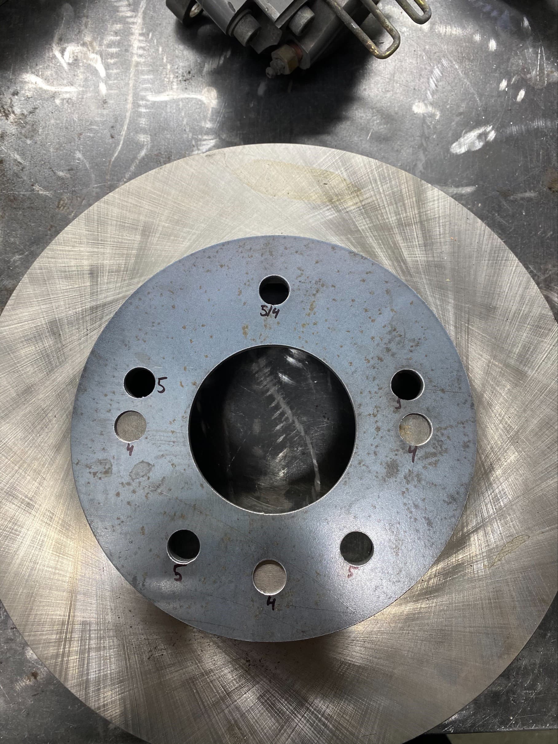
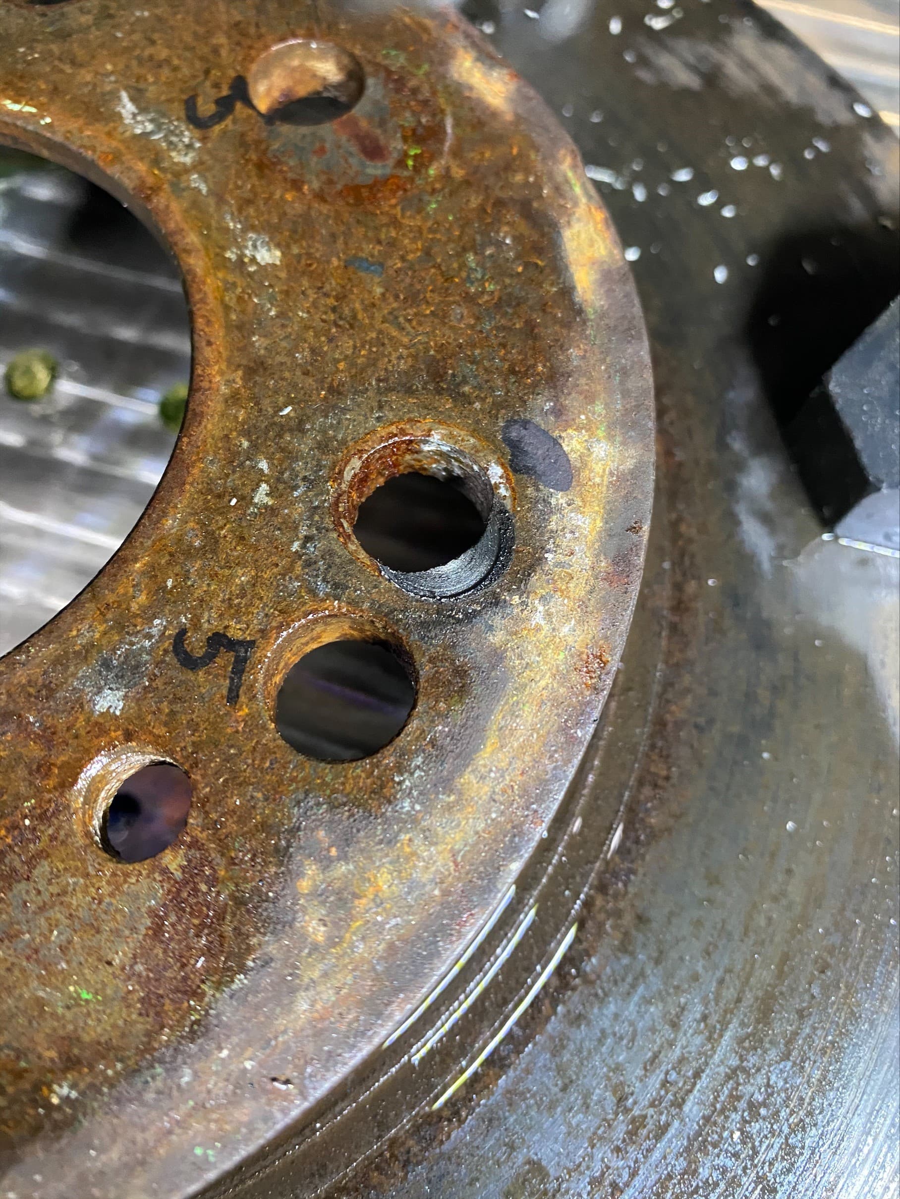
I loaded the old rotor and was going to run the program on it first, just so if anything were to happen I wouldn’t have a now useless new rotor. As you can see the first hole is off. My origin is set to the one hole that you reuse from the 5 lug pattern to the 4 lug pattern. I confirmed the origin is set perfect to 0 as these holes are 1/2" so I loaded up a 1/2" end mill and it perfectly slips into the hole.
I don’t understand what could be off. When making the bolt hole circle I used the create bolt hole circle in fusion. I’ve double checked all the dimensions in Fusion and it should be a perfect bolt pattern. Even my template I cut on the plasma table looks perfect. My stock size has no offsets, lead in/out are set to center. Not sure what else to check?
I just made another model without using the circular pattern feature in Fusion, and tried it as a drilling operation instead of boring, still same issue.
I would consider making a fixture plate that has a locating post or bolt hole for the hole you intend to use.
Have the WCS be a zero located in tbe bottom left corner of the work piece of fusion whicb represents an intersection point of two X/Y axis trued vices that are aligned to the WCS zero.
The rotor should be able to rest on vice faces and form a tagent off the two circumfrences.
The boring operation would just be the 3 remaining holes.
Set up the stock dimention to diameter of the rotor.
I’m not sure if this will help. I’m new to the stuff too! Here’s a few things you can try
I don’t think you can bore a 1/2 inch hole with a 1/2 inch end mill, try changing to a quarter inch and Mill. If this is the issue you should be able to see the problem in the fusion simulator or the MR one simulator.
Maybe set your center to the large center bore of the rotor (I always run the program twice as itself centers itself the first run, probably not needed though) and boring all of the holes instead of reusing one. This way you know you’re starting from center and don’t need to worry about lining up the rotor holes manually, It will all be done in the program.
If it’s still out of whack, then I would double check your step calibration on the machine.
How are you making sure that the rotor is lined up with the X/Y axes? Even with a good location on the one hole at the origin it’s still possible for the rotor to rotate around that point.
Unless your probe is calibrated perfectly it will be hard to hit your target. I’d set my zero to the center of the hub bore and dial it in with a coaxial indicator. They’re sorta expensive but really handy for a job like this.
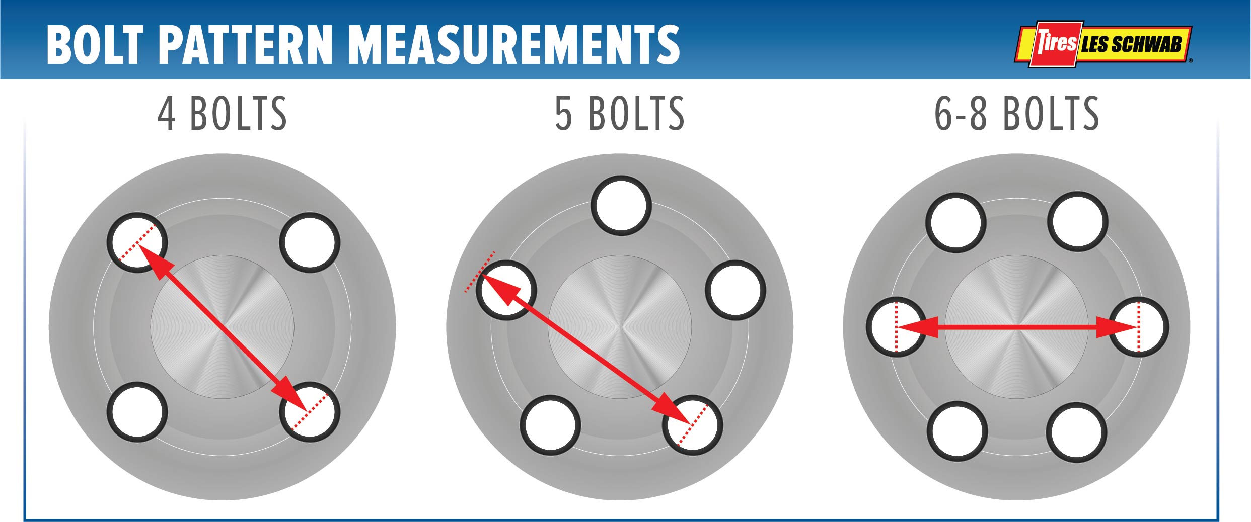
Wow DonP, according to that picture, you cant use any of the 4 holes as a starting point. the pattern would end up 1/2 a hole out of center. I never knew that about wheel lug patterns.
thanks
Bob
We redrilled all the time on a bridge port using a standard DRO and the hole pattern tool and always picked up off one of the holes. Id recommend using an online calculator to give you coordinates for your drawing, ive also done that. Then machine a quick boss matching the exact diameter of your rotor. Indicate off center. Start the program, stop right over the first hole, rotate rotor untill the drill will slide in smooth (just loosen collet nut) Clamp the rotor down and restart the program.
I also vote for setting the WCS origin to be the exact center of the disc. Use an inexpensive wobbler style edge finder. That should be able to get you within the backlash limits of the machine. E.g. Amazon.com
You can’t use a boring cycle with an end mill of the finished diameter, true, but I use center-cutting end mills with a drilling cycle with great results.