I cannot jog my x axis! HELP. All other functions work y axis and z axis. X axis does nothing at all, it is as if there is no power to the stepper motor, fire control thinks it is moving and reads a move but in reality nothing is happening with the x axis. All connections have been good. Used machine last week, everything worked great and now my x axis is a dead stick. No humming from stepper motor on x. The other steppers hum a little at idle. I dont know if the lack of humming is any kind of a tell as to what may be wrong.
If it were me I would swap the suspect motor into the Z connector on the control box and try to jog Z and also put z onto x and try to jog. You can test motors and drivers that way.
1 Like
Will do. Just happens to be really bad timing for me, i have a sign to make for a navy freind who is retiring. Hopefully i can get to the bottom of this.
So x axis moves just fine when hooked up to z axis. Opened control box and no lights on x axis driver. Guess i am out of commision😭
you could try to go old school to get the sign done. The OG crossfire did not have torch height control. So you might be able to swap the drivers and set the height manually. I believe there are different settings on the driver for Z and X so be sure to keep track of all of that. I would see if someone with more knowledge than me thinks that’s ok but it might get you going long enough to get a new stepper driver. I would contact @langmuirsystems support to verify the stepper driver failure they probably have additional troubleshooting techniques.
@TomWS @TinWhisperer you gus have any thoughts on that idea of swapping stepper drivers?
1 Like
@langmuirsystems do a pretty good job replacing parts in a hurry, but if all you need is a stepper motor driver then, depending on where you are, you could get one in a day from Amazon Prime. Look for TB6600 stepper driver, you’ll find tons of them. Personally, I don’t trust those crappy drivers and would get a DM542 from Amazon supplied by Stepper Online (the mfr).
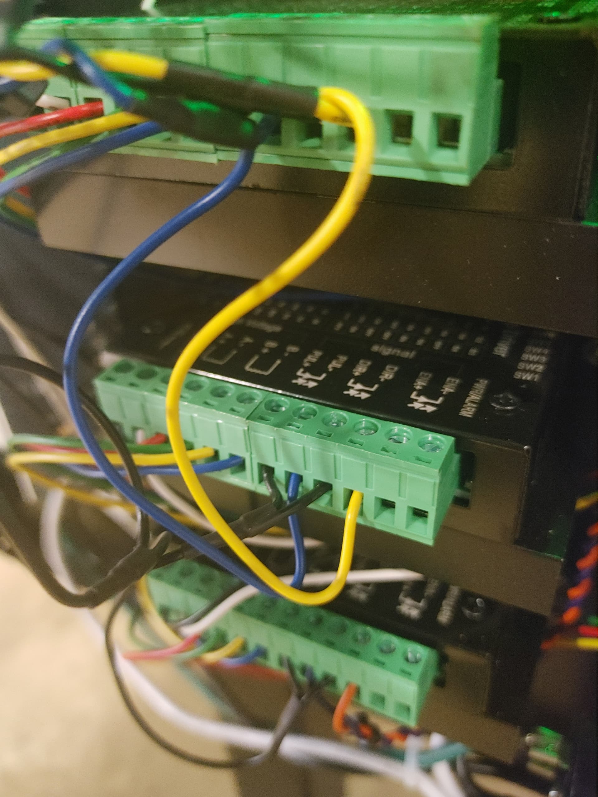
Before you do this, however, try reseating the plug in terminal blocks on the X Driver. Also, give a gentle tug on each wire to the terminal block. If not tightened properly they could come loose.
Be sure to check the little switch settings on the driver and make sure it matches the Y driver settings.
2 Likes
I have messed with the plug too no luck
Can you use a volt meter and on the input power terminals of that driver can you see if you have voltage.
Is this stepper something you have personally used and had luck with as a direct replacement? All i am finding is a dm 542T. Will this be right?
Looks like the other stepper driver is available on amazon.com.
I would check the incoming power feed to your existing stepper driver before you replace it.
Make sure you have the right voltage at the stepper driver or voltage at all.
1 Like
Yes, I have used the DM542T in my own designs and as a replacement for failed TB6600s. It is NOT a direct replacement. It is an improved stepper driver that:
- Doesn’t fail like the TB6600 crap that’s being shipped these days,
- Will be significantly quieter and smoother stepping than the TB6600.
It does require different switch settings to get the same current and steps per revolution as the TB6600. In this regard, you need to look at the existing driver settings to determine the current and steps per revolution and then set the DM542 accordingly. You will also need to transfer the wires between the two sets of terminal blocks as the terminals are probably different on the DM542. The ‘T’ version is just a newer version.
I should have the dm542t today, any help with setup would be much appreciated. I really have no clue where to set the dip switches. I would assume( i know now dangerous that is lol) that the order of all the wires and plugs is a match to the factory driver. If you could provide some guidence and or pictures of your setup that would be fantastic.
It would help a lot if you completely read my previous post.
Ok, try this…
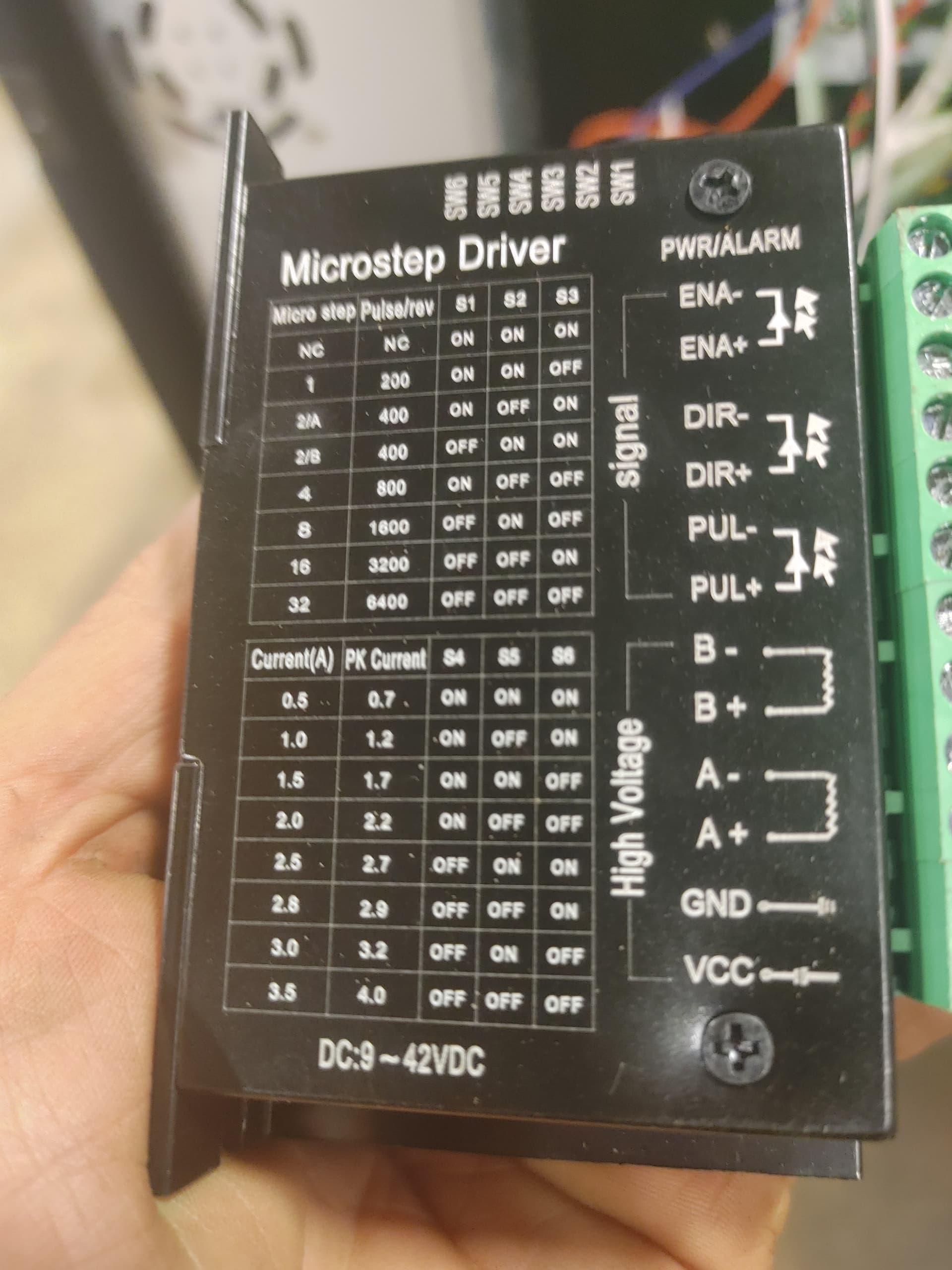
Look at your old X axis driver.
On one edge you will see SIX tiny switches in a plastic block. The switches are numbered 1-6 and the plastic block has writing that say which direction is ON and maybe which is OFF.
Record what each switch is set to, ON or OFF.
Look at the large side of the old axis driver and you will see two tables. One table is for switches 1-3 and one table it for switches 4-6. The table for switches 1-3 set how many pulses it takes for the motor to make one revolution. Match the switch settings to one row on the table. FOR EXAMPLE: if Switch 3 is ON but 1 & 2 are OFF then the row will be for 3200 pulses per revolution. MAKE A NOTE OF THIS.
NOW, look at the second table for switches 4-6. This sets the current for the motor. It could be that ONLY switch 6 is ON so the current setting would be 2.8Amps. Make a note of this.
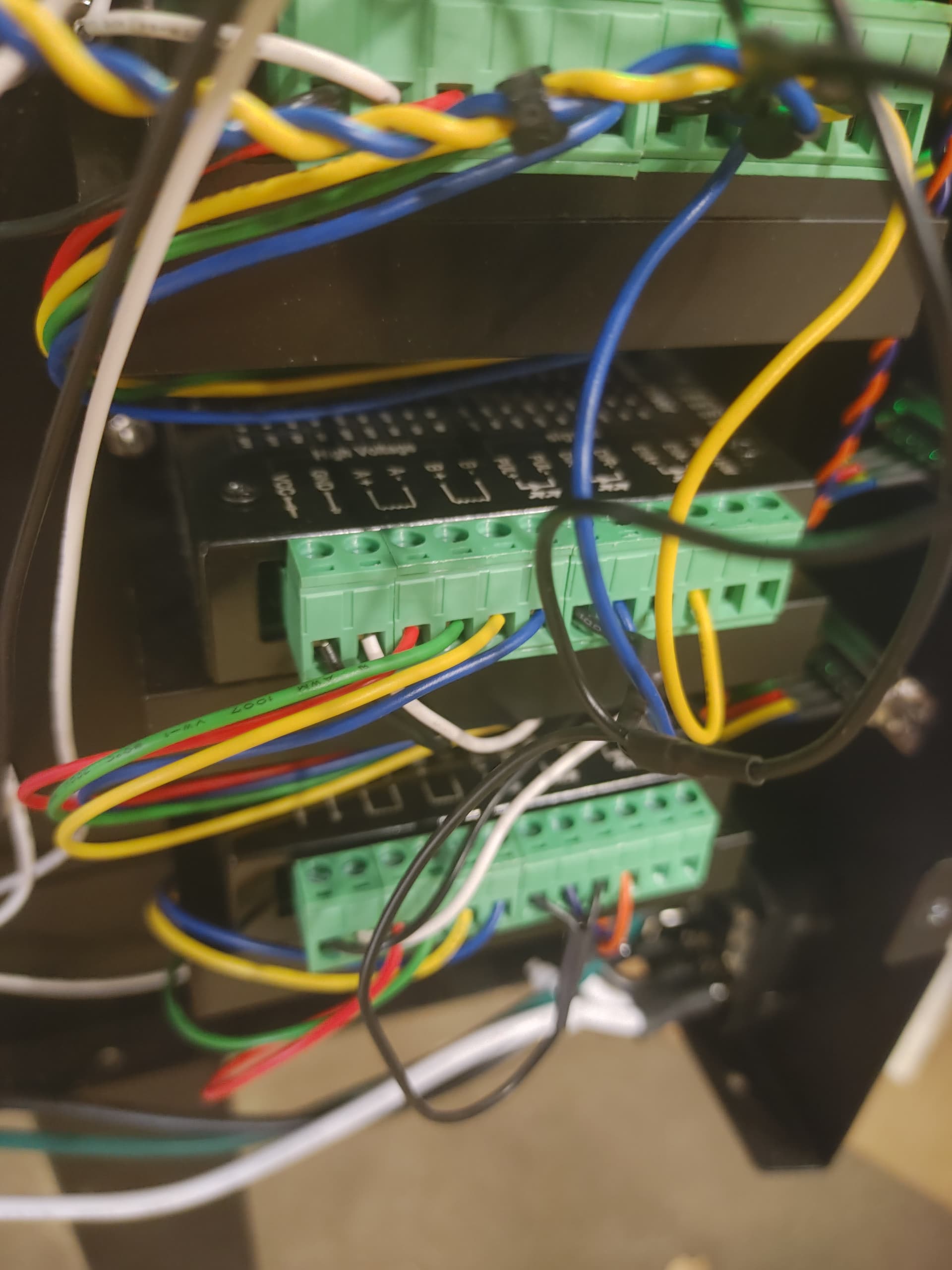
Finally, look at the wires going to each of the terminals on the terminal blocks. They are labelled:
EN-
EN+
DIR-
DIR+
PUL-
PUL+
B-
B+
A-
A+
GND
VCC
Record the color of the wire going to each terminal. There are probably not any wires on EN- or EN+.
1 Like
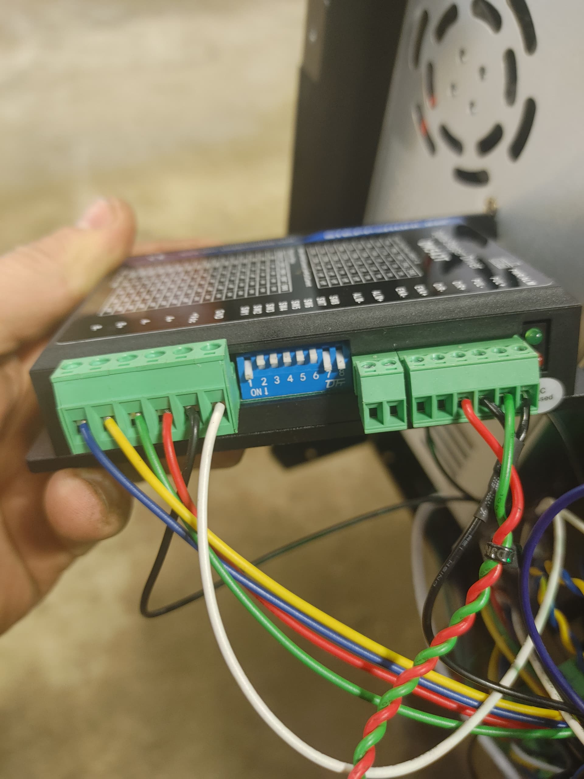
Hooking up the DM542T:
Look at the large side of the DM542T and you will see two tables, one for current, one for Pulse/Rev.
On this driver, switches 1-3 control the current. You want to set the current to be close to what the old stepper was. Let’s say it was 2.8 Amps. Looking at the table you’ll see 2.84 Amps as a choice. Close enough. So, to get 2.84A you need to set Sw1 & 2 ON, SW3 OFF.
Switch 4 can be left on or off, it probably doesn’t matter for an X Axis driver.
The second table sets the Pulses/Rev. Let’s say the old driver was 3200 pulses per rev. Look at the table and you’ll see that Sw5, Sw6, and Sw8 need to be ON, Sw7 OFF to get 3200.
Set the switches based on your old driver.
Now, transfer the wires, one by one to the new driver’s terminal block, matching each function to each wire. DIR+, DIR-, PUL+, PUL-. Ignore ALM+ & ALM-, they aren’t used for this application.
The motor and power wires are next. Note that they are ALMOST backwards from the TB6600. If you wire them completely backwards you will literally blow up your system!!! WHY? Because the order of VCC and GND is not backwards. The pins are different, but they are in the same order at the TB6600.
1 Like


Wiring and switches appear to be correct, although I can’t know which is PUL or DIR on your system (I don’t have a Pro).
If you have a multimeter, I can walk you through tracing out the wiring. Otherwise you’ll have to get Languir support involved.
1 Like
As far as using a multimeter i can follow along. Mechanically i am capable of anything, as far as the electrical knowledge i am a little lacking.