Before concrete coplanarity was shimmed to .0005.
After concrete coplanarity was reshimmed to get to .005 again.
Web calculator said to put two shims in top position, ran a rough on base plate and was easily able to catch a nail. Did some checks and the bottom needed to be shimmed and not the top. Removed the shims from the top and added the same amount in the bottom. Ran another small roughing pass and was still able to feel and edge but not nearly as bad. Ended up adding all the bottom shims in and got it to where there is hardly anything edge but there is still one present.
Now before I go about cutting more shim stock, is there an easier way to adjust this by shimming the spindle like others have done with the set screws?
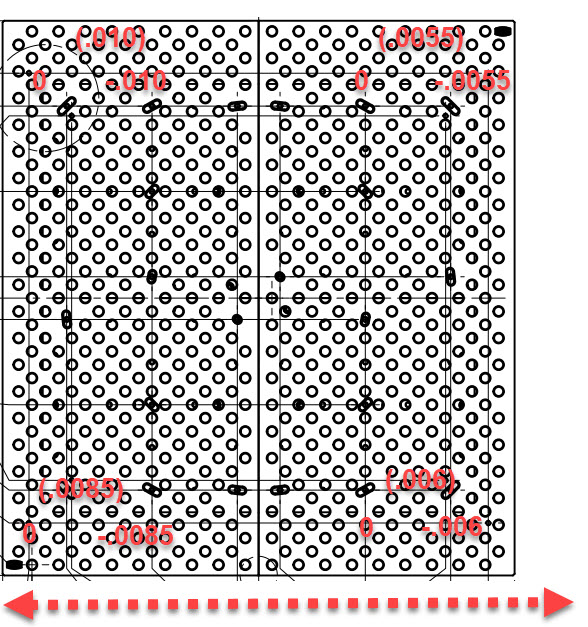
Attached are a couple photos with some measurements using the SST tramming tool. These are all based on measurements over 6" with the SST.
What would cause the erratic differences based on the measured location? Machine out of square I am assuming?
Quick question.
Are you shimming the spindle itself or are you shimming the Z axis casting where it sits on the X axis linear rails?
Shimming by their calculator was way off for me as well, but the shims that go between the cast carrier and X axis rails control the perpendicularity of the Z axis to the X and Y axis. Checked with a dial indicator on the side of a 1-2-3 or similar known square block by jogging Z up and down.
Shimming behind the spindle block would control the nod and the easiest solution for tram is the set screw method for ease of adjustment and being able to lock it all down once it’s dialed in.
Beyond those things it looks like you may have a little twist or non-parallel situation with the X axis rails which shows up as a difference from corner to corner and side to side. I did some reworking on my gantry to get the surfaces more true and still see a small deflection like this.
Yeah its the shims between the Z Carriage and X Axis linear rails. I assumed that the inconsistent readings likely point to a twist somewhere.
Ill go ahead and keep shimming the Z Carriage until I get an acceptable Nod. Once that is done I guess I will do the set screw mod to get the tilt out as best as I can and see what we have overall after all is done. Im just looking to get about .001 accuracy in all planes over a 4-5" span, so nothing major.
I ended up shimming that location to get the surface of the table flat enough to go back and shim it to properly align the Z axis.
It was so far off with to begin with that it had a .002" drop from pass to pass with a 3/8 end mill. Had to cram .024" of shim in there to get a flat enough surface to put a block on to even get started.
I ended up only needing around double the calculator amount to get the Z axis perpendicularity set. Then another .0025" on the lower spindle housing bolts to get the nod out with the spundle in the upper position. Tilt/tram was about .0025" over 6" but I did the set screw mod and got it down to .0015" over 8". Close enough for me
Hell yeah. Thats what I am going to do. I have the base plate roughed out with all of the bottom shims in and it got rid of most of the nod but there is still an ever so slight edge you can just barely feel. Ill continue to shim that out so the base plate is as good as I can see/feel then do the set screw mod/spindle bolts to dial in the remaining nod and tilt with the spindle in the up position.
Agreed the calculator is all of a waste of time. I wish they would revisit their build procedure and do an in-depth instructional on how to actually tram in the machines axis and why you need to do it. dimensionally accurate parts within a tolerance isn’t possible without going outside their calculator setup. I spent considerable amount of time dialing in the Z axis travel before I even thought about tramming the spindle. And I was coplanar to a tenth before and after concrete. so everything after coplanar post concrete build is a guessing game unless you spend time really getting the axis in line and accurate.
We were able to borrow a Starrett 123 and 246 block that is certified to .0001 from a machinist friend and get the nod to .0005 over 6". Tilt was spot on and if anything was within .0001.
We ended up having to cut one of the big .2mm shims and then use two of the included lower gantry shims to get it correct. This is way off base from the two uppers that the tool said to use, lol.
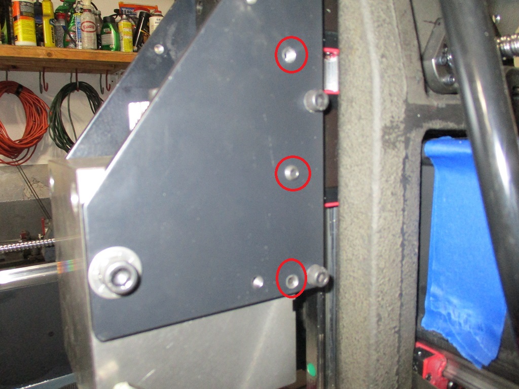
It is where you remove the side plates and drill tap some 1/4-20 holes. Then you install some set screws to to rotate the spindle block for proper alignment. I did 3 sets of holes so that I have 2 on each side for both the lower and upper spindle position.
My z travel was spot on with the shins from the calculator and thankfully, no twist to be found (since that’s an uncorrectable error).
My tilt and nod were both horrendous, shoving some 0.5mm worth of shim to get both to within 0.001” over a 3” radius with respect to the spindle’s rotation.
Has there ever been an explanation from Langmuir why the numbers can be so far off? My nod is way off and I wrote tech support for guidance. I want confirmation on what to do. No answer yet.