I keep trying harder and harder projects to see if they will pass muster and run the simulation in sheetcam. I would like some input on my latest crazy idea. I started with a photo of my beach buggy
and cropped and converted it to a bitmap. I imported the bitmap into Qcad and played with it and ended up with a dxf file. dunebuggy.dxf (982.2 KB) It will run in sheetcam with a zero offset. But is it too messy? will it crash halfway through? Am i a complete lunatic? I would love some constructive direction. It seems like im on the right track. I’m afraid of deleting too much of the drawing and loosing the character of my buggy.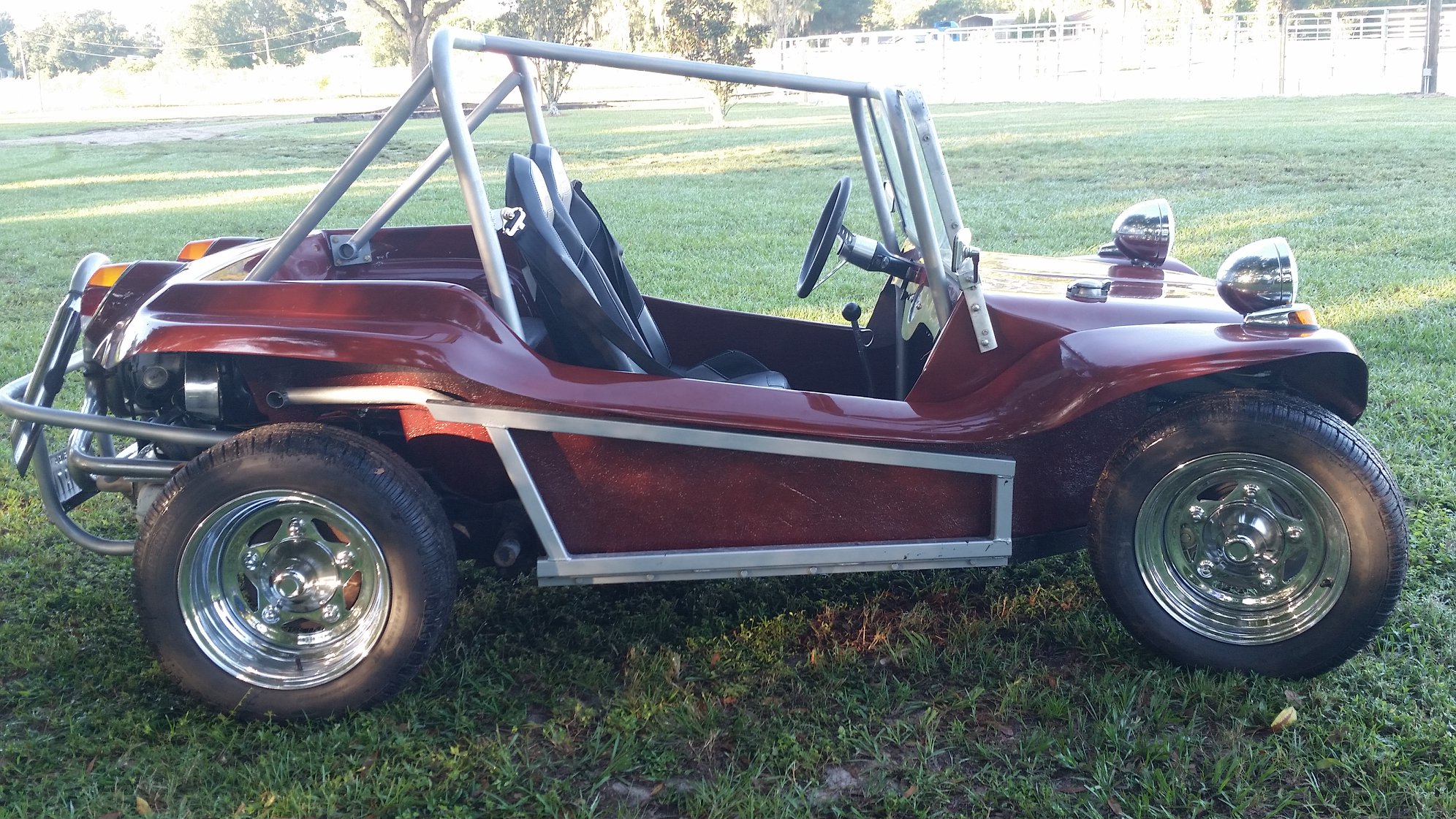
Did you draw all of this in QCAD or did you use bitmap tracing in another program to generate the paths?
They way you describe it makes it sound like you took the bitmap into QCAD and drew it yourself, but it looks like a bitmap traced file.
Short answer, no you’re not really close. There is a lot going on in there, some paths cross over each other, and it’s so confusing I can’t really pick out for sure what will and won’t remain if you were to cut it.
Using a program like QCAD to artwork like this is not ideal. I don’t believe you have the kind of control over arcs and paths like you would in a vector drawing program like Inkscape (free) or Affinity Designer (what I use , around $45 one time purchase).
If I was given this image by a customer I would import the image into Affinity and manually draw it out. The end result will be cleaner paths, and optimized for plasma. It would also be easier to visualize what it would look like also, because you could do it in black and white with black being the remaining metal, and white being the parts that you intend to have cut out by the plasma. This method takes some time and know how, but it’s how I create most of my files.
I also keep everything as .svg files. Sheetcam loves them, and I’ve never run into some of the problems others have with certain paths not being connected and not generating a path (seems to happen with fusion users).
Here’s a shot of it for others to chime in without having to download the dxf.

2 Likes
Thanks for the input. I’m not sure where to begin tracing this by hand. My “art” skills are building things, not drawing them. I’ve watched a bunch of videos and tried a bunch of stuff. (MASSIVE fail!!!)
I have inkscape and have not been as successful at using it as I would like.
Yeah I hear you. It’s tricky for sure. I’ll try and do a video for my channel that covers how I do this stuff. I recently did a Godzilla for someone using this method.
This is the only pic I have of it on my phone. The final version fixed the weird hand and opened up some of the negative space to allow it to cut with a .06 kerf.


I agree. Much of the tracking is of highlighted areas from lighting effects in the original picture. Those don’t either add or detract from the essence of the buggy. Using the original picture as one layer and then drawing over it using the drawing & bsplines tools would get the major definitive shape lines. And then just delete the photo layer.
1 Like
I agree with @brownfox and @jamesdhatch. You may like the look of the photo but the bright sunny background, shiny chrome full of reflections, shiny hood, will all drive any tracing program bonkers. If you could take a new photo with a totally neutral background and indirect lighting, you might get something you could touch up (I doubt it due to the chrome). However, as the others said, taking the photo you have, it’s a simple thing to scale and then trace the ‘essence’ of the vehicle. You’ll be surprised how impressive even a simple metal piece can be.
1 Like
thanks for the encouragement guys. I’ll keep plugging away at it. That’s how I learn
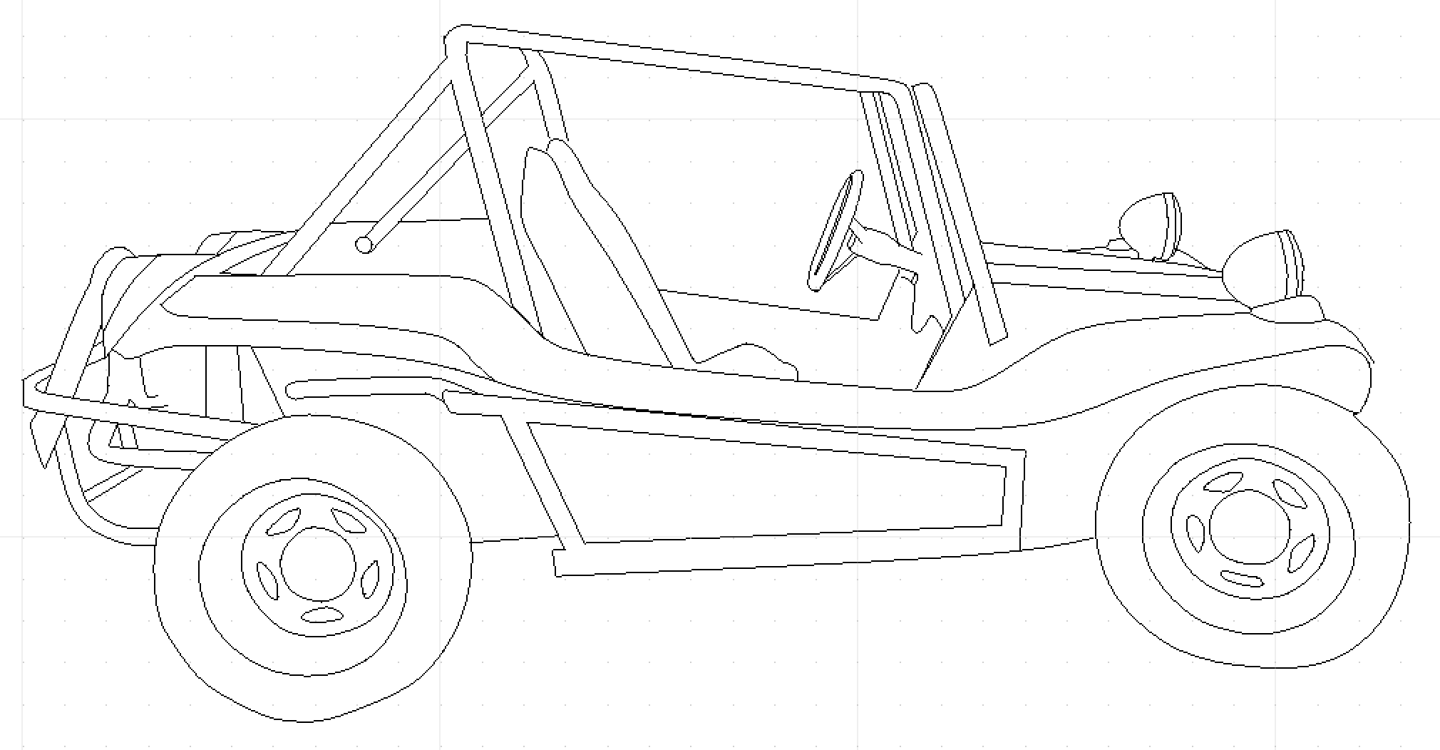
So I’ve been playing hardcore with inkscape and I’ve been able to draw this.
![]()
Now my question is what to do with it next. What would you guys recommend to make this a good sign file? I think it’s cool because it’s my personal dune buggy. ![]()
no picture…sorry…but it is blank
I cant seem to upload it. the file name appears in the box when I’m typing, but wont show up on the post. any ideas?dunebuggy trace.dxf (99.7 KB)
When I click upload and browse for the file the preview panel says uploading, but nothing happens.
EDIT: it uploaded a dxf file fine. but the svg wont upload.
Import the svg into sheetcam and create your tool paths, or are you asking for design ideas to make it work as a sign? Export it as a jpg and post it.
I’m looking for input on how to make a cut-able sign from it. I’m having trouble visualizing which pieces will fall out and which ones will stay. Should I “dead end” all of the lines so there is no cut through? If I do that how do I keep the marks from lead in and lead out from ruining it?
I’m at my work computer without a sheetcam license, Is that why I can’t export as a JPG?
No, I mean post a jpg of your Inkscape design
1 Like
Yes. Just a soon as I get home. Thanks
Cool. It sounds lazy to say I don’t want to download it and open it on my computer, but I never check the forum from a computer. Always my phone when there’s down time. Lol
ahahahahahaahhah…
I don’t see the option to save as a jpg? I can save as a PNG but when i upload it is too dark to see.
It’s really hard for me to describe how I would turn this into a sign. I’d have to see the svg file and see what you did complete paths for. I would make all the fill black with white stroke, and then using the add and subtract features in affinity (I don’t know what Inkscape calls it) I would bridge some of the features, and turn some of the lines into open contours to give detail that can’t be cut all the way out. Like what I did with the bear’s paws on the tree.

2 Likes
Thanks. ![]() it’s a lot more work than I expected.
it’s a lot more work than I expected.
So do you cut those area with no lead in or lead out? I was thinking of making all the paths open, so that only a couple of features fall out.