I retrofit my machine for LinuxCNC using a Mesa 7i96. I thought I’d share my notes, which would be helpful to anyone considering alternative controls (I’ve seen Masso, Acorn, and Mach4 all mentioned on here):
I’ll keep updating as I figure out new things. I’ll also put my LinuxCNC config files in the notebook once I’m happy with how everything is working (I still need to configure the probes).
In addition to the stock MR-1 hardware (plus probes) I also have the spindle encoder working. My setup has an extra stepper drive so I can add a rotary table in the future (I already have a small CNC Sherline one from a prior machine) and enough remaining I/O for me to switch to a ATC spindle.
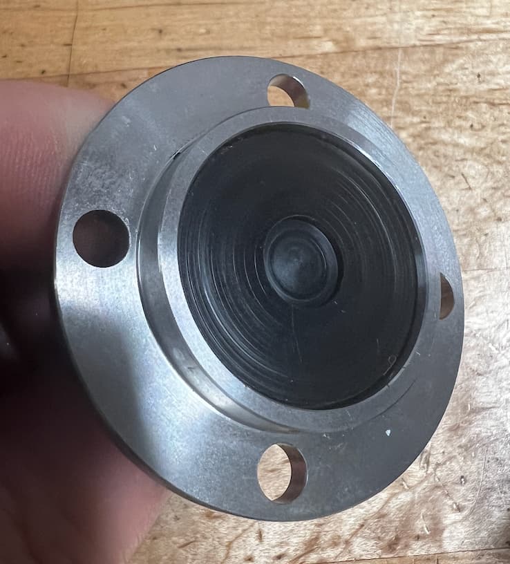
One tricky thing took me a while to figure out. The Langmuir touch probe exposes it’s 5V input to the shaft, which will short out to ground through the spindle encoder ground. Langmuir seems to handle this by fully isolating the 24V power supply from the rest of the DC using a B0524S-2WR2 (isolated 24V from 5V).
I solved it by disassembling the probe and making a small delrin insert that fits between the spring (which is 5V) and the top/shaft of the probe, isolating the probe.
Brilliant idea to log your build details using OneNote Alex. I really appreciate you sharing that. I just got my Centroid package this week and I’m watching your thread closely as this conversion will be my first.
I hope everyone else doing conversions also shares what they learn and notes on how they approached it. We can build up the wiring diagrams and technical documentation that isn’t a part of the package.
I should have figured this out earlier, but the tool setter probe has the same design (the touch pad is at 5V DC). I remembered when taking apart my spindle control cable from Langmuir that they had cut one of the wires. I checked and it was pin 12 (analog input ground). If you connect this to your DC negative it will ground the spindle motor to your DC negative which causes these probes not to work.
The solution is to let pins 11 (encoder ground) and 12 (analog input ground) on servo CN1 float. An alternative would be making a insulating pad for the touch probe, and installing it on a plastic block.
Langmuir’s probe and tool setter are nicely made, but I question the design choice of making all exposed metal surfaces at 5V DC.
Sorry not much of an update yet. I get the new control enclosure awhile ago. It’s 24” x 24” x 10” deep. Hope it has enough room. I also got all my DIN rails. Need to sit down for an afternoon and lay everything out. And order servo motors too. Unfortunately knee deep in landscaping my new house.
I swapped out my stepper drivers from the stock TB6600-based ones to Leadshine EM542S. These are running smoother and faster (I’m running at 180ipm now and that doesn’t seem to be near the limit). These steppers let you tune them to avoid resonances, which I haven’t done yet. This upgrade was well worth the $200 for me.
I have manual tool changing completely automated. It uses the tool setter to probe between tool changes and automatically probes the height of the tool setter when you have the probe in the spindle. This makes manual tool changing less error prone. I like how CutControl did the measurements (figuring out the relative difference in height between the tool setter and workpiece), so I copied that design in my scripts.
My next step is adding an exhaust fan to the control box. There is no ventilation at all next to the stepper drives, only by the servo drive. I expect that this was done to keep chips out, but I’d prefer to have fan with filter fabric to let everything run cool.
Now that my machine is all dialed in I have to get back to making some stuff!
I tried this add in with cut control and it ran fine until my manual stop where I wanted to do a tool change and wouldn’t let me do anything unfortunately. Hopefully whenever batch posting is possible I’ll be able to make it work
Can I ask how did you wire it compared to the existing Y axis drivers and what was your pins setting for these leadshine e542S. I found on amazon the stepper online version e542T for $21 that I would like to explore. Thanks
StepperOnline has the DM542T which doesn’t allow for software tuning but is still probably a nice choice.
The cable pinout is listed on both the stock driver and the Leadshine ones, so it is easy to swap it in. Make sure to flip the switch for 5V signaling (leadshine default is 24v) and to set the same microstepping of 1600. Also match the amps for the motor, I used the same setting as on the stock drive.
These use a different mount spacing than what is in the Langmuir case. I made an adapter plate out of 1/4” thick aluminum that has holes for my new steppers and which is through bolted from the backside using the original hole location.
Are you using 180ipm as rapids only or are you able to cut at that feed rate? Are you seeing the ball screws starting to whip at that speed? The stock steppers have plenty of power with the proper driver but the ball screws look awfully small.
I’ve cut soft materials (foam and plastic) at those speeds, but the spindle RPMs are too slow to take advantage of them for cutting aluminum. Mostly it’s helpful for rapids when measuring tool offset, doing tool changes, moving between vises, or other long moves.
@MrmachineTX asked if I’ve gotten the spindle working in reverse.
I haven’t tried it. I’m slightly interested so that I can try the RapidChange system, but there are multiple other things that will be obstacles too. The biggest is that the RapidChange intentionally stalls the spindle when tightening the collet, and since the spindle on the MR-1 is a servo this will put the servo into an error state which the controller will need to reset. The servo documentation is unclear if they can reset this error through a soft reset or if it will require a power cycle, and I haven’t intentionally stalled my spindle yet to try it out.
From my reading of the servo control documentation you have to go into reverse by providing a negative speed voltage. I haven’t wired my controller to allow this. The other option would be to configure the controller for step/dir mode, which I haven’t played with but should provide superior speed control.
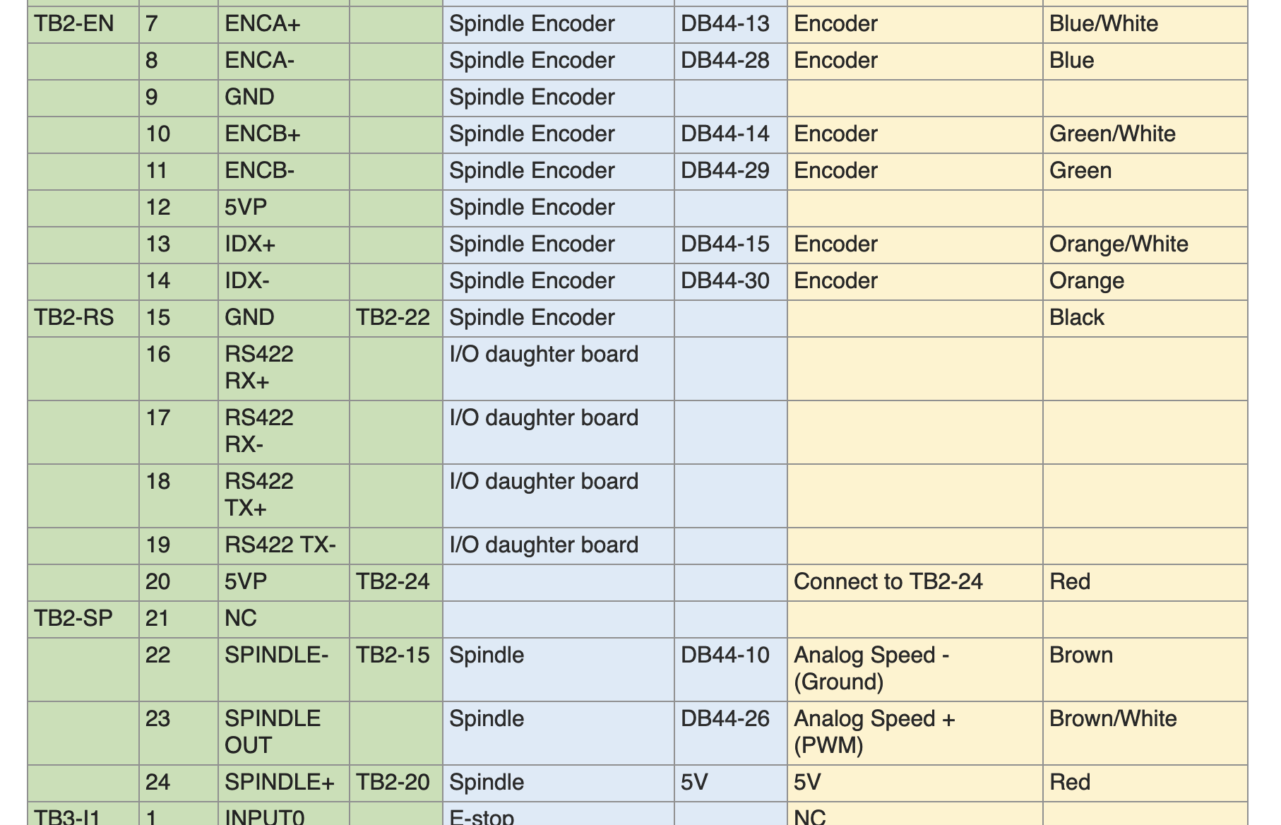
The pinout table in my OneNote is going to be useful to anyone rewiring to a new control. I recommend making a copy of it into Excel and then replacing the left side with the wiring for your control system:
Also read the wiring notes, you have to be very careful with grounds when working with the MR-1 – if you use the Langmuir probes you have to be careful to isolate DC and AC grounds.
I made a quick (and low quality) video yesterday showing the current state of my conversion. I have a new spindle setup and doing quick tool changes:
Full ATC is the next logical step and mostly a matter of programming at this point. I’m not sure that I’ll go that far – I use the machine primarily for one-off/prototyping type work and don’t need the machine to run completely lights off.
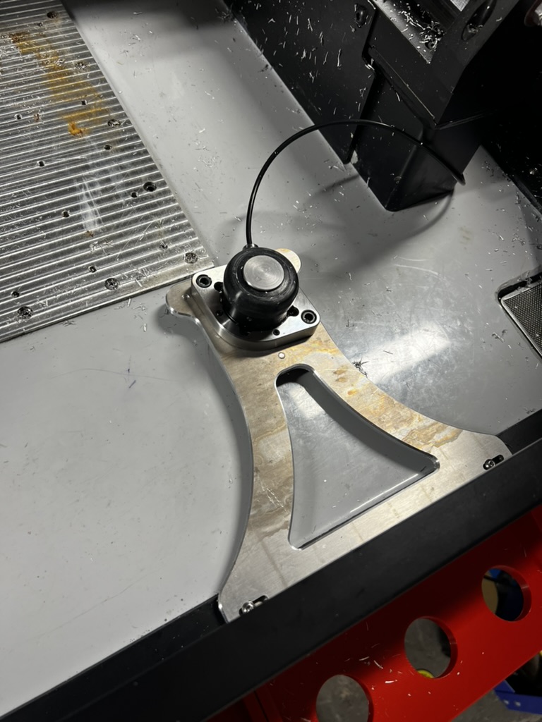
I also moved my tool length probe off of the table to the front of the machine. This should be doable with the standard probes as well, and of course it frees up the full table for work projects.