Great video! I subscribed
Langmuir posted the MR-1 GRBL firmware source. Thank you! The useful part of this for us doing conversions is that we can get the constants for the machine configuration:
I had to figure out a lot of these values experimentally, but it’s great to have a good starting point for anyone swapping controls.
#ifdef DEFAULTS_LS_MR1
// LS MR-1 CNC Defaults
#define DEFAULT_X_STEPS_PER_MM 320.0
#define DEFAULT_Y_STEPS_PER_MM 320.0
#define DEFAULT_Z_STEPS_PER_MM 533.333
#define DEFAULT_X_MAX_RATE 2540.0 // mm/min
#define DEFAULT_Y_MAX_RATE 2540.0 // mm/min
#define DEFAULT_Z_MAX_RATE 1016.0 // mm/min
#define DEFAULT_X_ACCELERATION (300.06060) // 106060 mm/min^2 = 10 mm/sec^2
#define DEFAULT_Y_ACCELERATION (300.06060) // 106060 mm/min^2 = 10 mm/sec^2
#define DEFAULT_Z_ACCELERATION (50.06060) // 106060 mm/min^2 = 10 mm/sec^2
#define DEFAULT_X_MAX_TRAVEL 580.0 // mm NOTE: Must be a positive value.
#define DEFAULT_Y_MAX_TRAVEL 550.0 // mm NOTE: Must be a positive value.
#define DEFAULT_Z_MAX_TRAVEL 150.0 // mm NOTE: Must be a positive value.
#define DEFAULT_SPINDLE_RPM_MAX 9000.0 // rpm
#define DEFAULT_SPINDLE_RPM_MIN 0.0 // rpm
#define DEFAULT_STEP_PULSE_MICROSECONDS 10
#define DEFAULT_STEPPING_INVERT_MASK 0
#define DEFAULT_DIRECTION_INVERT_MASK 0
#define DEFAULT_STEPPER_IDLE_LOCK_TIME 255 // msec (0-254, 255 keeps steppers enabled)
#define DEFAULT_STATUS_REPORT_MASK 0 // WPos enabled
#define DEFAULT_JUNCTION_DEVIATION 0.01 // mm
#define DEFAULT_ARC_TOLERANCE 0.002 // mm
#define DEFAULT_REPORT_INCHES 1 // true
#define DEFAULT_INVERT_ST_ENABLE 0 // false
#define DEFAULT_INVERT_LIMIT_PINS 0 // false
#define DEFAULT_SOFT_LIMIT_ENABLE 0 // false
#define DEFAULT_HARD_LIMIT_ENABLE 1 // false
#define DEFAULT_INVERT_PROBE_PIN 0 // false
#define DEFAULT_LASER_MODE 0 // false
#define DEFAULT_HOMING_ENABLE 1 // false
#define DEFAULT_HOMING_DIR_MASK 1 // move positive dir
#define DEFAULT_HOMING_FEED_RATE 100.0 // mm/min
#define DEFAULT_HOMING_SEEK_RATE 762.0 // mm/min
#define DEFAULT_HOMING_DEBOUNCE_DELAY 250 // msec (0-65k)
#define DEFAULT_HOMING_PULLOFF 1.5 // mm
#endif
2 Likes
A big difference here in their configuration and mine is the acceleration values. Langmuir uses much more conservative configuration, which makes a lot of sense to make sure that users don’t experience stalling. I run 100ipm^2/s (42mm^2/s) on X/Y and 40ipm^2/s (17mm^2/s) on Z and have found higher values to be really useful with high speed machining. I’ll change my github notes since people follow those for conversions to show Langmuir’s conservative settings as the best starting point, and higher ones as what may be achievable with new drivers and power supply.
2 Likes
Thanks for posting this Alex.
Alex, the tool setter standoff looks pretty spiffy.
Did you add adjustable legs under it for support over the epoxy?
Yes, there are some hex head screws under there that are adjustable feet to support it on the epoxy and to allow for minor leveling adjustments. If you click into the big version of the photo you can see the tops of two of these as little stainless dots.
@AlexW do you have any pictures from your stock → LinuxCNC conversion? (That is, the Mesa board with stock drivers and minimal changes to stock wiring).
I am working through your wiring table / notes on OneNote & GitHub and have a few questions that may be answered by that picture.
-
ENA+ / ENA- are not connected to the stepper drivers by default, however you are connected to both of them in your diagram. In your parts list you had a 4x terminal phoenix connector. I assume we shuffle the 2 pin Phoenix connectors and use the 4x Phoenix connector on the last stepper? I’m not sure the difference between enabling the driver from EN+/- or VCC/GND. I suppose the ability of having the EN pins on an output allow selective control of the steppers, but to me if the mill is on we would want the steppers energized.
-
How do you manage your grounds? I have seen the other posts mentioning isolating the touch probe, but do you have a separate ground for +5 / +24 / +36V as it appears?
-
This is not a question, but LS’s choice to go with White = Negative / Black = Positive has caused me a ton of confusion
-
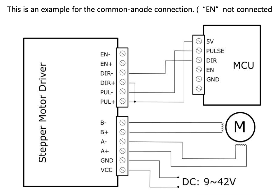
EDIT: I had previously thought these were differential signals (relative to each signal + / -) but my understanding now is that they are single ended and active low. Also, I noticed PUL+/DIR+ on the MR1 controller are both tied to +5V, do these need to be connected directly to the controller? The controller has separate +/- channels for both pulse and direction.
EDIT: I decided to use DIN terminals to join common signals together (such as +5V / +36V). Similar to previous question, how do you manage jumping multiple terminals on the 7I96S? I am using ferrules and can potentially squeeze two into one
Once I finish my build I will post my notes here. Thanks!
I did my initial conversion in the Langmuir box and with their spindle servo. I can dig up pictures of that if helpful. I had a common DC negative across all of my DC power supplies.
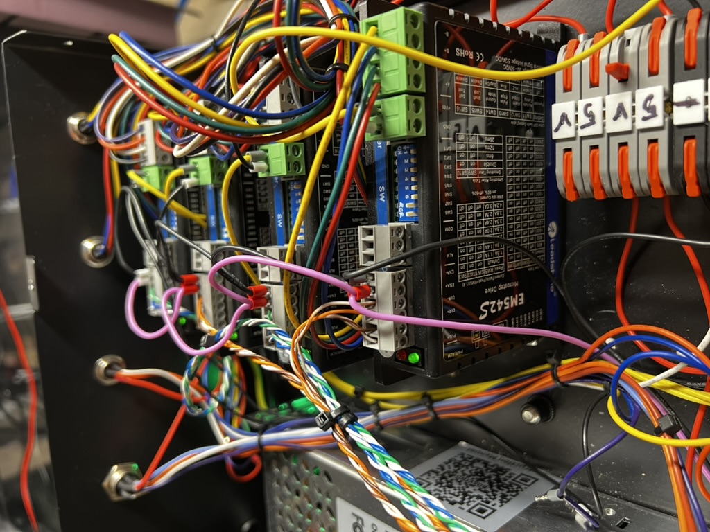
Here are some photos. The purple line is the ENA circuit to the 4 stepper drives. These aren’t the same drives that Langmuir used, but they have the same enable circuit (including the odd choice to have 0V be enabled).
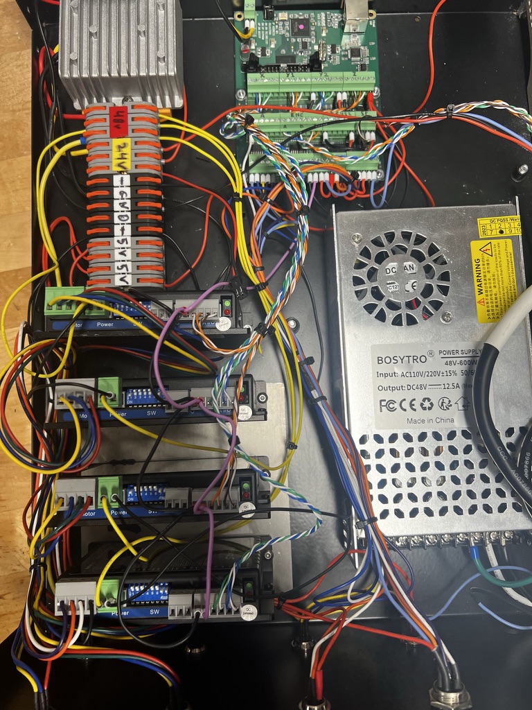
This is the general layout that I used, with the Mesa 7i96s mounted near where the original CutControl/GRBL board lived:
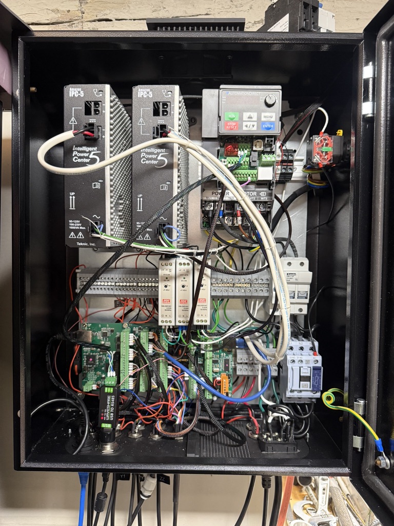
I’ve since completely redone my control in a new wall-mounted cabinet and using Clearpath servos. I wish I had replaced the control cabinet earlier, it’s much easier working with this one that has an opening door and where it is mounted at roughly eye height. The two power supplies in the upper left corner are for the servos.
1 Like
Awesome! Thanks so much for the feedback. I rewired the step / direction channels and am able to get the X and Y axes homed properly, however when the Z axis attempts to home it gives a “Cannot home while shared home switch is closed j=3”.
As I understand it, each X / Y / Y2 / Z axis is numbered 0 - 3, with Z being 3. Since Y2 and Z share a pin on the controller, an error is thrown because the program is not aware that the Y2 and Z limit switches share the same circuit. Is my understanding correct?
I’m not sure what exactly I’m missing here since I’m able to get the Y axes homed without it throwing an error saying that the Z axis limit switch is enabled.
Thanks again for your help!
Is Y homed and sitting on the homing switch? Try moving it off of the homing switch by a few mm, then homing Z. I have my homing sequence setup to always move off of the homing switches after homing.
You do this by configuring HOME and HOME_OFFSET. For instance on my Z HOME is 0, HOME_OFFSET is 0.050. Since Z goes from 0 to -6 that sets the homing switch (HOME_OFFSET) as 50 thou above 0. When it homes the axis goes all the way up to the homing switch, then drops 50 thou and will never go up to the homing switch again in normal use because my MAX_LIMIT=0, MIN_LIMIT=-6.
2 Likes
I’ll take another look at my wiring. I’m using your LinuxCNC configuration for the stock MR1 spindle. Both Y axes move during homing and appear to not be in contact with the limit switch.
I will say that if you have a spare input you’ll find it easier to just have a unique input for each homing switch. That is the configuration that I’m using now. However this would require redoing the harness if you are using the Langmuir homing switches.
1 Like
Great idea. I added the Z axis to its own input and it attempts to home but the Z axis does not move. I swapped the STEP/DIR from the X axis to the Z axis and was able to get the Z axis moving when jogging in X.
I also tried swapping the Z axis STEP/DIR to the X axis but it did not move when jogging in Z. Any thoughts on this? Sorry for all the questions but I really appreciate your help.
LinuxCNC generally won’t let you jog any axis until it has homed on gantry machines. It assumes the gantry isn’t properly aligned until homing is complete. It should give you an error stating this.
If it thinks Z is moving during the jog you’ll see it update the DRO values.
Is your homing speed set too slow on Z, like close to zero?
1 Like
Understood, the DRO is moving at a pretty normal rate during homing. Doesn’t seem like the Z axis is set to home slowly.
Update: I moved STEP/DIR for the Z axis from axis 3 to axis 4 and it moves! (in the wrong direction). I am wondering if something with my 7I96S is messed up with the axis 3 control.
Ooh, glad you got it working. Do you have an oscilloscope? They are cheap these days, and would let you check the signals on the 3rd port.
Wrong direction is normally fixed by changing the direction to seek in the homing config. Check the docs, I think it is a sign on homing speed or something like that.
Recently, around September, I got a completely bad MESA 7i92 board for a customer and a good bit of the GPIO did not work. I don’t know if the had a bad batch of chips or it was there assembly.