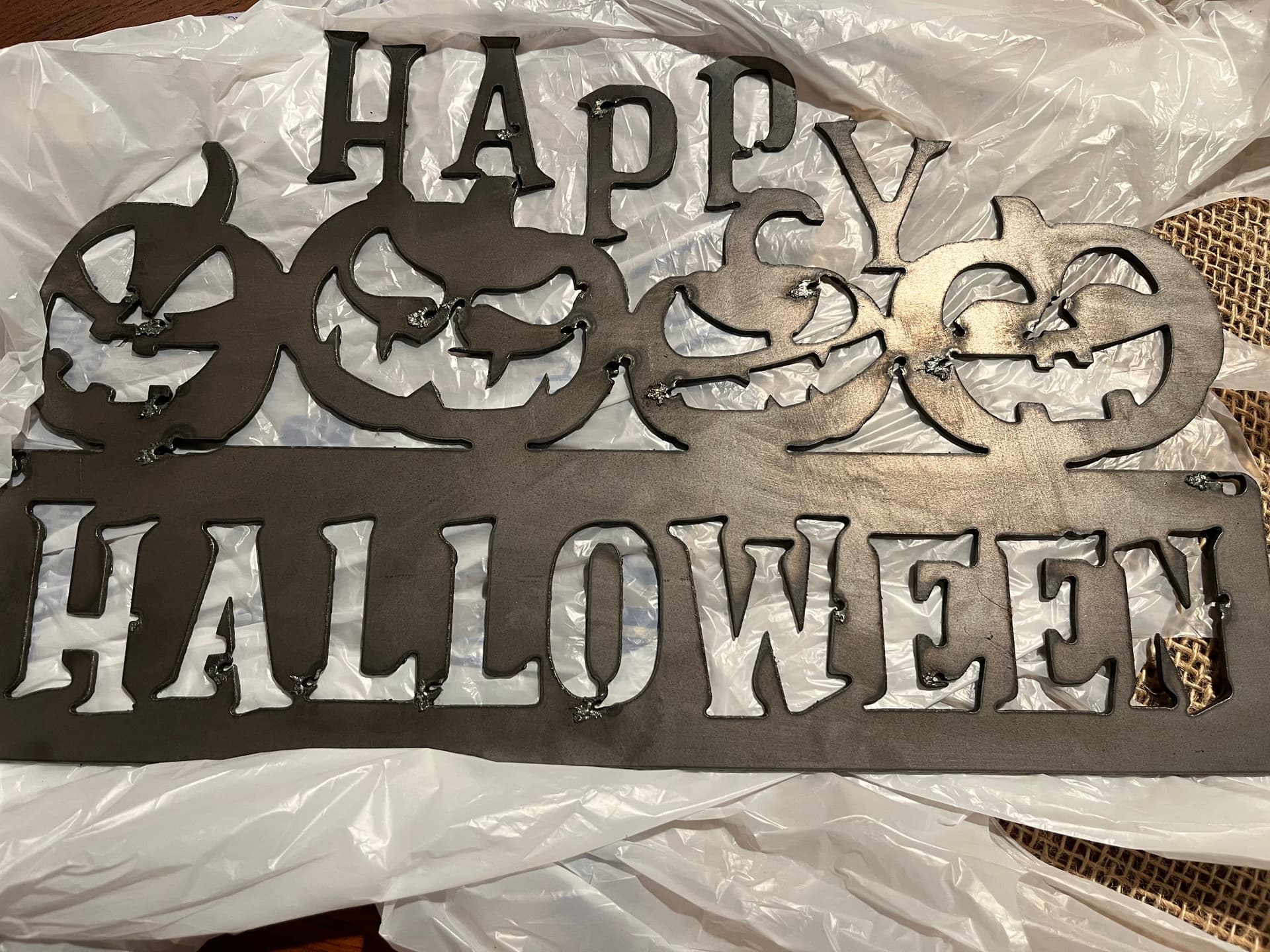
Wondering if anyone can point me in the right direction, I received the part that I needed to finally try my table. I cut this program b/c it looked fairly easy to try without wasting too much metal. The holes by the cut outs are large? How can I minimize the holes that I think are the starting points? Thanks for any help
2 Likes
It appears your piercing straight on the line being cut or on the wrong side of it.
Have you configured any kind of “ lead in “ for your tool path
3 Likes
Its piercing into good material which make me think the wrong offset is selected (it thinks you want to keep the inside parts), which is strange as sheetcam is usually pretty good on auto detecting that stuff.
1 Like
I don’t use Sheetcam but my suspicions are that you have Interior set to Exterior or whatever the setting is.
Meaning, your inside cutouts are recognized as outside cutouts hence the lead in cutting outside of the letter to start versus inside.
1 Like
Thanks for all the responses, yes I’m using sheetcam b/c I found fusion 360 way too hard to learn for an old man. I’ll try your suggestions.
Always select “outside offset” and let Sheetcam assign the proper offsets when you are doing a single operation to cut the whole file.
If you select inside offset, it will reverse all of the offsets and you will get lead ins on the piece instead of the waste.
1 Like
I realize the challenges with F360. I have not tried sheetcam. So I am unaware of how F360 setting will translate into Sheetcam
On ART projects I use NO lead in or lead out. I have my kerf set to zero and I use a 1/2” overlap on closed loops.
I also cut outlines clockwise and all other feature counterclockwise. This is sent up into F360 and happens automatically. I have occasionally had to edit a cutline and change the direction but this is every rare.
The biggest thing I have to do on any art project is check to make sure I have at least 1/8” between any cutlines so the feature is not obliterated by the plasma arc.
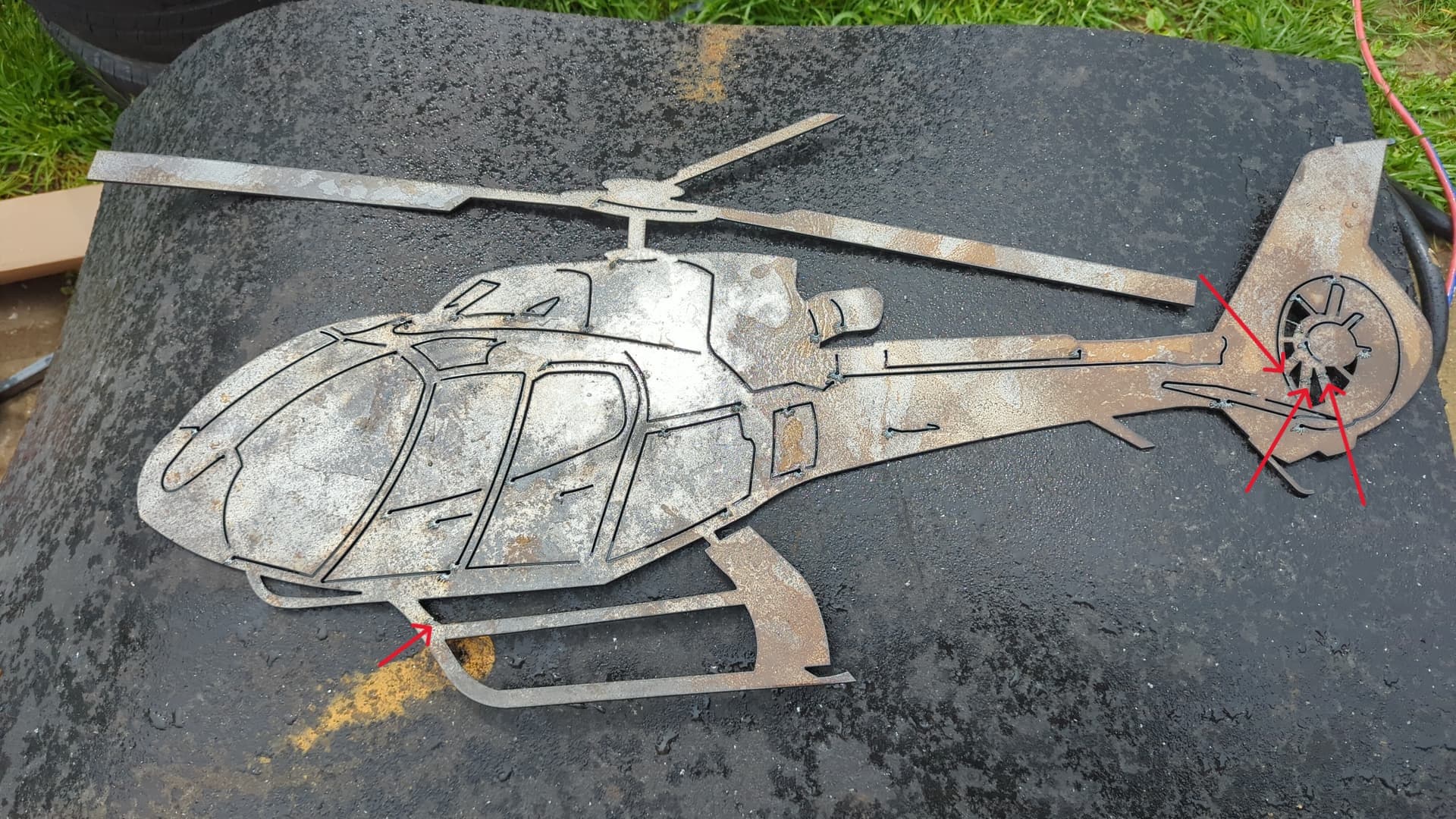
This helicopter is tip to tip 40” wide 20” tall. The smallest feature at the tip of the tail the top line in the tail rotor is 1/16” wide. Very narrow cut for a Rzr45 set to 40 amps

1 Like
If you upload that file you cut I will edit it tonight with F360 and send it back. However, I can’t do it until later I have to help family today.
You will need to upload the original file you started with not the sheetcam file you used.
Really cool cut out!
The difference with what you show versus the author is that you are displaying many ‘open chains’ versus the author’s closed loops.
You are correct in that open chains do not use any lead in, or lead out, and you also remove pierce clearance with a center compensation. But these are not settings to be used on closed loops such as the landing skid.
Utilizing a “no lead in” value can cause burn marks where the pierce begins in a closed loop which for many is unappealing. Closed loops are indeed where you want and need a lead in to hide those burns, and using a specific lead in on a specific section of that loop can make all the difference.
Just take this as constructive criticism, you can definitely make this better!
2 Likes
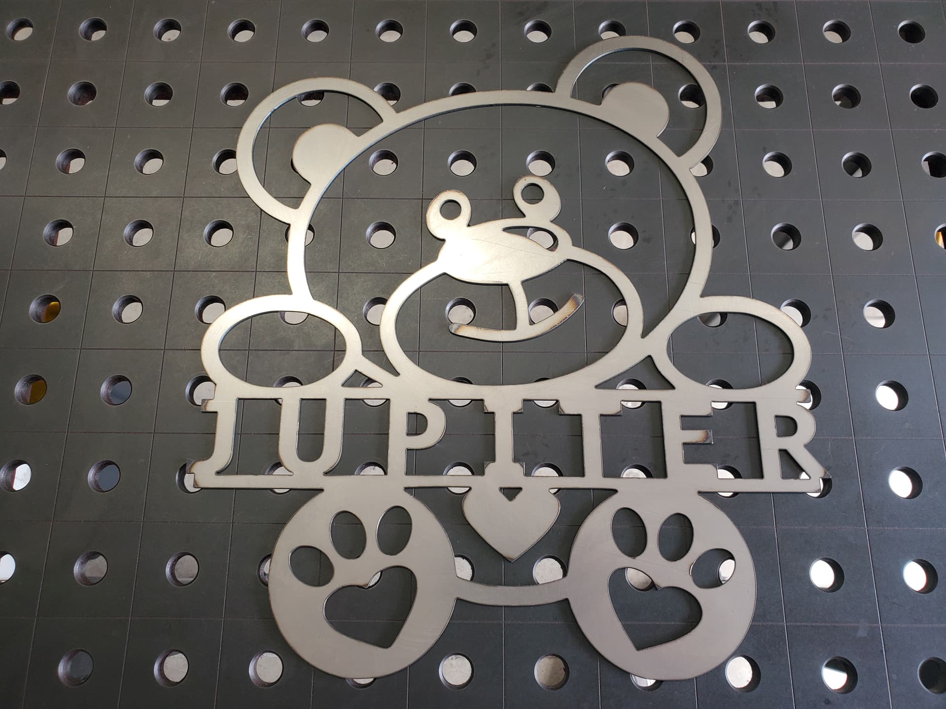
Very nice clean bear.
The issues is when I do very fine closed loop detail F360 will not cut the fine detail because there is not enough clearance to accommodate the lead in or lead out. And so far I have not found a way to program individual lead in and lead outs of closed loops. So For “Art work” I use the method above and complete my work.
There are times that the contours are just too small. At that point, you will need to ask yourself “Is the divet more acceptable than a single line or even no line?” Here is how I added an additional toolpath to go after those discarded contours:
3 Likes
When I need to make Items “Clean” I’m having no issues with lead in and lead outs. For “Art Work” I do not have anyone complaining about my art work. When I have needed clean line on art pieces I just make 2 programs and run one of the lead in/outs and one with the straight line cuts.
So far so good.
1 Like
I have no problems with your projects. They look great. I was only trying to help address your comment which I took to mean you wanted some suggestion(s).
1 Like
Nope the original poster had trouble with his cut. I had offered to edit the file with the setting I use. Kwikfab shared is very clean cut bear. I appreciate the suggestions. Information is always good.
1 Like
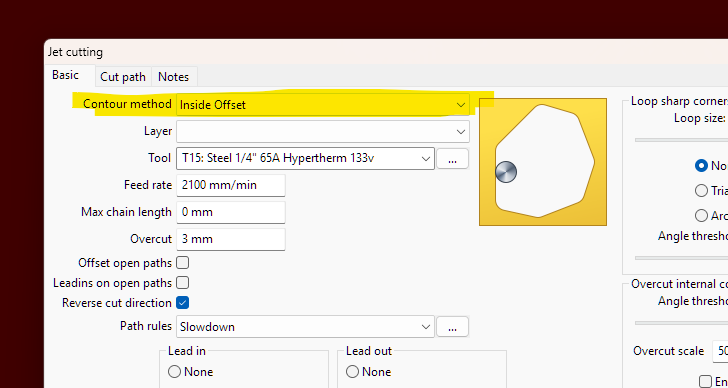
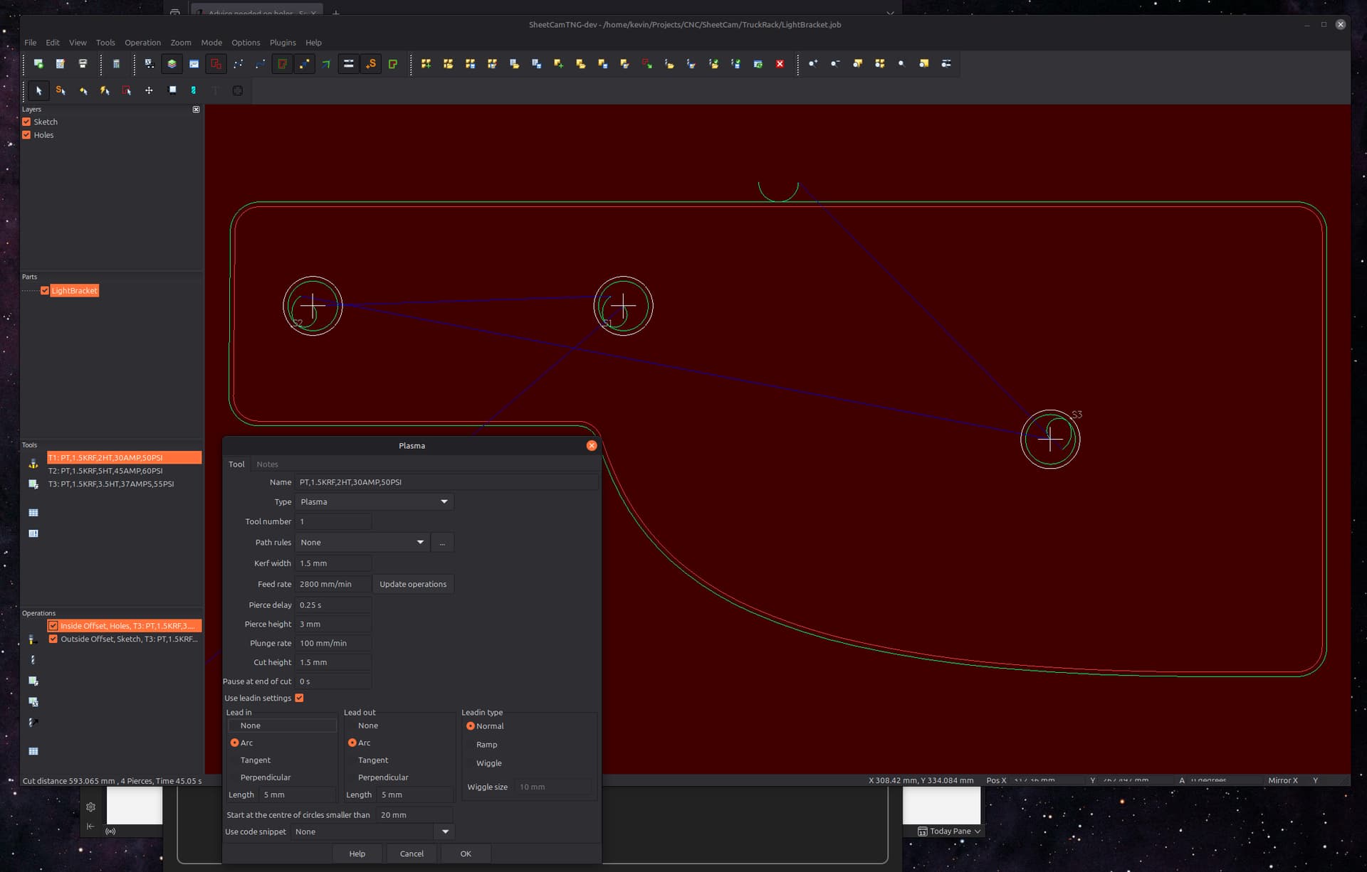
With SheetCam I select all the inside cuts and put them in a new layer and choose inside offset.
I leave all the outside cuts in the original Sketch layer and for that choose outside offset.
I choose a 5mm arc into the cuts and a 5mm arc out of the cuts. I also choose to start at the center of circles smaller than 20 mm.
I cut all the inside offset (holes) first. Then I cut the outside offset (perimeter) last since it’s holding all the holes securely.
I included a screen shot to help you see my settings. This works and makes nice clean lines inside and outside.
Did you know sheetcam will choose the correct side of the line if you want to do a single operation. The only time I do layers is if I need different lead in lengths or doing a file with only part of the contours.
It is easier to do what works for you. It is just one less step.
2 Likes
Thank you for the suggestion! I think early on I saw SheetCam choosing which side of the lines to cut, but after a cutting mistake (probably because I didn’t have a contour closed and failed to proof the cutting paths) I decided to assign offsets manually to have a step in place to watch this. I’m better now with drawings and proofing cutting paths, so maybe on the next project I’ll allow SheetCam to select the offsets automatically and see what I think about the workflow.
1 Like
make sure you have outside offsets selected the yellow lines will be inside and red will be outside white are open lines. it will cut yellow on the inside red on the outside and white center. as long as you have a work around it works.
3 Likes
Just to toss out another option in sheetcam that can be used on a single shape basis…
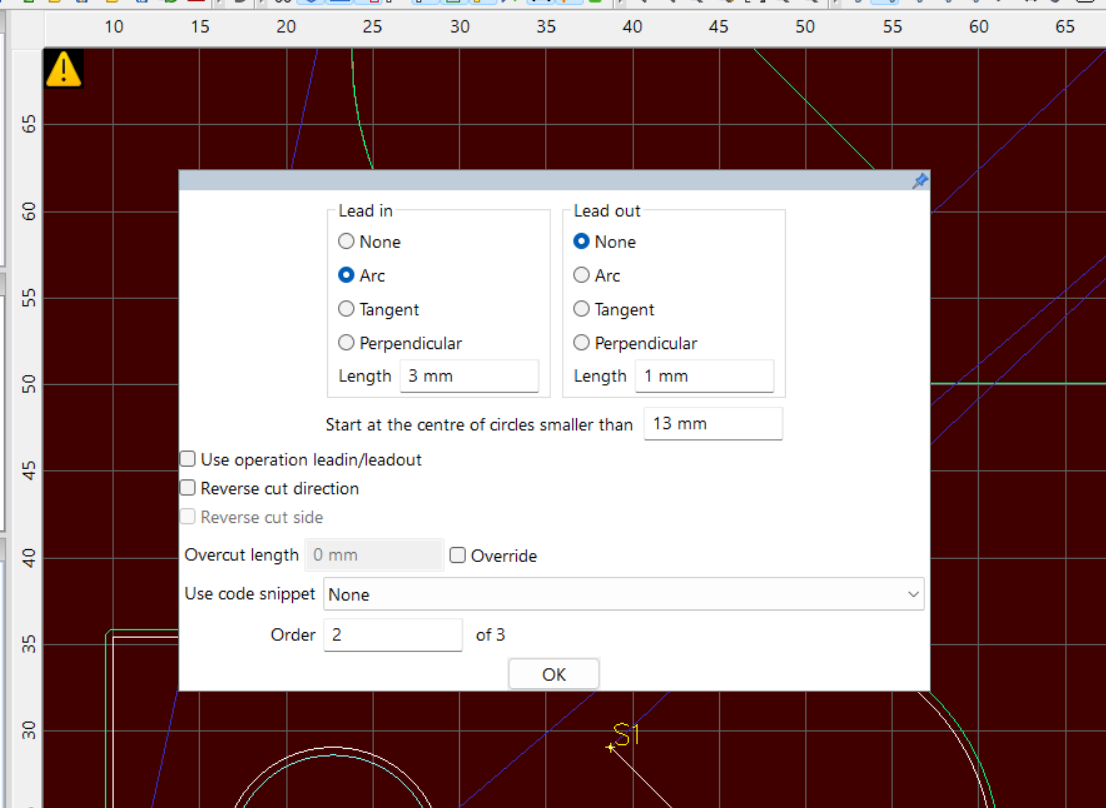
If you ever find you need to alter the start point parameters of just one shape, use Mode / ‘Edit start point’, then right click on the start point in question, select ‘properties’ from the context menu, and you can alter those params on the pop up window for just that start point. It’s handy sometimes when just one or two shapes are an issue out of many.
2 Likes