I haven’t gotten super deep into accuracy yet, but I’m largely not impressed so far, only able to hold reliably within about 0.012" when all is said and done.
I’m not convinced it’s the machine itself, based on my check with the 1-2-3 blocks, I actually think the axes themselves are very accurate (and I spent a lot of time dialing them in). I think the issue is coming down to probing, setup and workholding (Low profile vises, yes I did crack the screws loose so they pull the part down into the parallels). I’m curious if anyone has knuckled down and dug into improving accuracy and if they have any advice?
I’ve seen the Haimer 3D probe thrown around a few times, but it’s kind of spendy and I don’t love the idea of manually probing everything.
I’m not trying to reliably hold tenths, but would love to be able to easily hold within 0.002" and within 0.001" with some effort.
I’d be curious to check the repeatability of the axis and the fixturing. I know you said they are accurate, but writing a short program or using the jog controls to move a few inches back and forth to see how close they come back. Also check the repeatability of how the vise is pulling your parts down.
The probes could definitely be improved. Even with going through mine and doing all I can to make it operate consistently I get about .005 repeatability on X and Y from one part to the next.
All that said, I generally hold about .001" thickness on parts in my vise, and the machined diameters and lengths are pretty spot on after dialing in backlash and travel comps. On any new setup I always raise my Z about .010" and adjust it after verifying thickness when milling to a finished height. Even on bigger industrial machines there are times that a work or tool offset is off by a few thousandths.
I initially thought the probe was the way to go, but for me, it wasn’t always accurate so I couldn’t trust it. Manual probing is a PITA…but it is accurate. I don’t mind as I’ve been doing it that way for 30+ years. I use an edge finder for X and Y.
For Z, I use a precision ground dowel pin, move off the part, jog Z down the OD of the dowel pin, and then zero Z. Results are always a 0.001" or better.
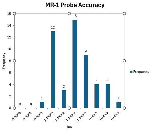
There seems to be a lot of variation in the stock probe. I’ve had mine apart a few times and I think that cleaning it and careful reassembly has been key to getting better repeatability. I wrote a script to test my probe for 50 cycles and was getting repeatability within 0.0003 (clustered at under 0.0001):
I was getting much worse results earlier, and cleaning and careful alignment is all that I can attribute the improvement to.
When putting it back together machine sure that you properly align the 3-legged spider. It can go in 3 ways, but only one of them is correct.
I also keep my probe always aligned the same way in the collet. You can do this on the stock spindle by keeping a dedicated collet nut for the probe. I always have the cord come out to the front.
I guess I’ll have to try a repeatability test. I think I’m seeing some kind of drift with every new setup, especially in Z. Not sure if it is the probe or the tool setter. My most recent part, batched 5x for each setup, was about 0.018" undersized in thickness by the time I had flipped it 3 times. Most other things were in the 0.001"-0.005" range of precision (the biggest offender being an undersized interpolated bearing hole).
This all feels like it’s more difficult than it’s “supposed” to be… but my background is in engineering design where all I have to do is put ±0.002" on a drawing and the part shows up in spec (usually ). My day job company just ordered a Tormach for engineers to prototype with… and if this is par the course, the other engineers are in for a rude awakening.
I didn’t remove and reinstall. I could do it now that I have automatic tool changing working, though I’m not sure of the value. You can also just measure runout of the spindle. Runout of the collet shouldn’t be an issue if you always use the same collet (as suggested earlier) and keep the probe and collet oriented the same way.
I use an edge finder. After endless trial and error with the touch probe, I was unable to produce reliable results in x and y. Using it for Z and tool setter offset seems to work perfectly, but I have now resorted to touch off on shim and offset adjustment. I have considered a 3D gauge, but I see a probable issue with the tool setter/3D gauge compatibility.
I’ve replaced the control system with LinuxCNC and the spindle with a CNCDepot FM30F. If you search for my old posts you can find links to all of this information, including youtube videos and a github with the software configuration.
I bought my MR1 knowing that I’d probably replace the full control system and electronics. It was still cheaper and better suited to my work than the Avid Benchtop Pro that I was consider. I surprised myself by keeping the 4 stock stepper motors – but everything else that has electrons running through it has been replaced.
You can do it incrementally over time, but the key first step is replacing the control system. Cut Control is not modifiable so doing anything interesting is going to require replacing it. It is also very limited in functionality, so just doing this step opens up many more interesting ways to use the machine.
I think of the machine as a kit and I used most of it.